


1. All electrical work must comply with applicable local
electrical codes.
2. The DH unit should be connected to a properly grounded
dedicated branch circuit of proper voltage rating. In
installations with several DH units, each unit requires an
independent circuit. Please refer to the technical data table
for the correct wire and circuit breaker size.
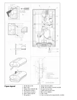
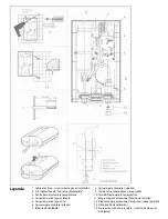
3. The wire must be fed through the cable seal (9) in the rear
cover. Guide the unit over the mounting screws and slide it
downwards. Connect wires to wiring block.
4. Reinstall plastic cover and secure with screw.
5. Turn the temperature control knob from left stop to right
stop. Internal setting lever will engage.
1. All plumbing work must comply with applicable regulations
of the local water supply company.
2. A pressure reducing valve must be installed if the cold water
supply pressure exceeds 100 PSI.
3. Make certain that the cold water supply line has been
flushed to remove any scale and dirt.
4. Cold water connection (inlet) is on the right side of the unit,
hot water connection (outlet) is on the left side of the unit.
NOTE: EXCESSIVE HEAT FROM SOLDERING ON
COPPER PIPES NEAR THE DH UNIT MAY CAUSE
DAMAGE.
5. Tankless water heaters such as the DH series are not required
to be equipped with a Pressure and Temperature Relief Valve
(PTRV). If local codes require it, it should be installed on the
hot water outlet side of the unit.
6. The unit has a 1/2” G connection on both the hot and cold
water side. Braided flexible connector hoses HAVE to be
used. If the unit is connected with hard pipe the inlet filter is
not accessible.
7. When all plumbing work is completed, check for leaks and
take corrective action before proceeding.
Electrical connection
WARNING: BEFORE BEGINNING ANY WORK ON
THE ELECTRIC INSTALLATION. BE SURE THE
MAIN BREAKER PANEL SWITCH IS “OFF” TO
AVOID ANY DANGER OF ELECTRIC SHOCK. ALL
MOUNTING AND PLUMBING MUST BE COMPLETED BE
FORE PROCEEDING WITH ELECTRICAL HOOK UPS.
WARNING: AS WITH ANY ELECTRIC APPLIANCE,
FAILURE TO ELECTRICALLY GROUND UNIT MAY
RESULT IN SERIOUS INJURY OR DEATH. THE
UNIT’S PLASTIC COVER MUST BE INSTALLED BEFORE THE
CIRCUIT BREAKER IS TURNED ON.
Putting the water heater into operation
1. With the circuit breaker off, open the hot water valve until
all air is purged.
2. Turn on circuit breaker to bring electrical power to the unit.
3. Set knob to desired temperature.
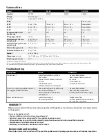
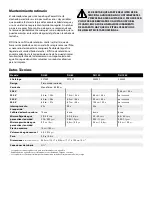
Normal Maintenance
The Aqua Power DH series of tankless heater is designed for a
very long service life. Actual life expectancy will vary with wa-
ter quality and use. The unit itself does not require and regular
maintenance. However, to insure consistent water flow, it is
recommended to periodically remove scale and dirt that may
build up at the aerator of the faucet or shower head. Also, the
DH unit has a built in filter screen that should be cleaned from
time to time. In order to do this, the flexible hose connector on
the cold side (right) has to be disconnected. The inlet filter is
inside the inlet fitting.
Clean the housing with a damp cloth. Do not use any abrasive
cleaning agents or agents containing solvents.
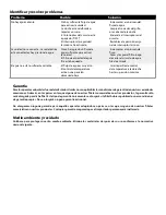
OTHER THAN THE FILTER SCREEN, THE DH UNIT
DOES NOT CONTAIN ANY PARTS SERVICEABLE
BY THE LAY PERSON. IN CASE OF MALFUNCTION
PLEASE CONTACT A LICENSED PLUMBER OR ELECTRICIAN.
Water Connections
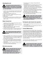
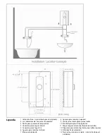
Mounting the unit
THE UNIT MUST BE INSTALLED IN A VERTICAL
POSITION WITH THE WATER FITTINGS POINTING
DOWNWARD. DO NOT INSTALL THE UNIT WHERE
IT WOULD BE ROUTINELY SPLASHED WITH WATER. ELEC-
TRIC SHOCK MAY RESULT.
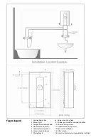
1. Install DH unit as close as possible to the hot water draw-off
point, for example, directly underneath the sink or next to
the shower stall.
2. Unit must be installed flush with the wall.
3. Leave a minimum of 5” clearance on all sides for servicing.
4. Release screw, securing cover.
5. Remove cover.
6. Determine the position of the holes and drill holes to mount
the unit. Insert the wall anchors and screws insuring the
depth is correct.
Summary of Contents for DH 100
Page 1: ......
Page 13: ...Notes Notas ...


