Aqua Lung Legend LX Second Stage Technical Maintenance Manual Download Page 10

10                                                                                                                                                  Legend LX Second Stage Service Manual

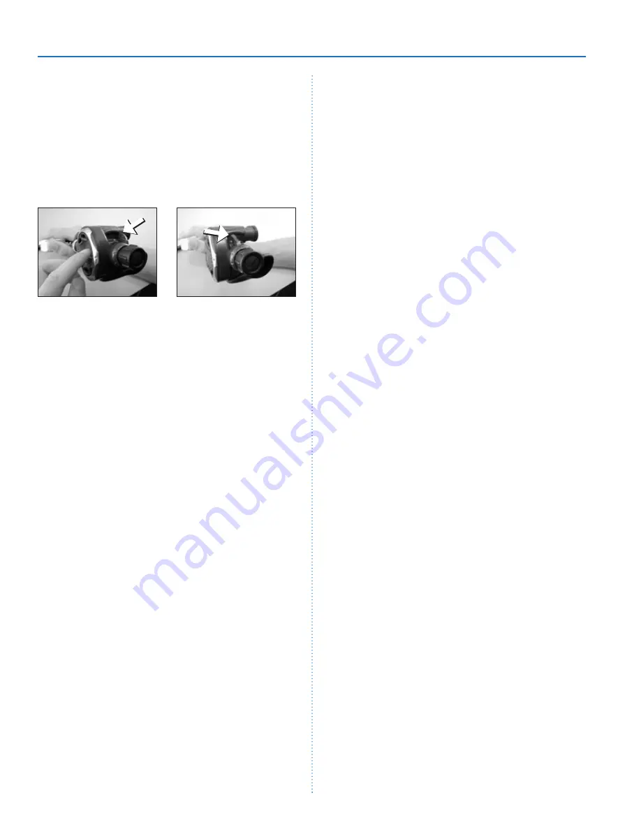
21.    Perform the venturi test:

a.      To test the venturi control, place the lever in the 

plus position.

b.      Depress the purge cover. You should get loud, run 

away freeflow.

c.      While the regulator is freeflowing, move the venturi 

lever to the minus position. The freeflow should 
stop abruptly. If it doesn’t stop abruptly, the crown 
orifice may be out too far. Try turning it in (clock-
wise) 1/8 of a turn and try again.

of H

2

O for a standard 2nd-stage, or +1.1” to +1.7” of 

H

2

O for the supreme 2nd-stage.  If the reading exceeds 

these specifications, refer to refer to “Table 1 - Trouble-
shooting” for corrective actions.

Second Stage Air Flow Test 

1.      Slowly turn the flowmeter control knob until the flow 

reaches a minimum of 15 SCFM (425 liters per minute).  
The reading on the Magnahelic gauge (inhalation / exha-
lation effort gauge) should indicate no more than +6.O” 
H2O.  If the reading e6.0” H2O, refer to refer to 
“Table 1 - Troubleshooting” for corrective actions.

Second Stage Purge Flow Test

1.      Turn off the flowmeter control knob.  Next, while the sec-

ond stage is still mounted on the mouthpiece adapter, 
watch the flowmeter gauge and depress the purge 
button until the second stage valve is completely open.  
The flowmeter gauge must indicate a minimum of +10.0 
SCFM (284 Liters per minute.).  If the purge flow is less 
than +10.0 SCFM, refer to “Table 1 - Troubleshooting.”

2.      When purge flow is correct, remove the second-stage 

from the mouthpiece adapter on the flow test bench.  
Shut the valve of the test bench, and purge the second 
stage to depressurize the system.  Remove the regula-
tor.

External Leak Test 

1.      After disconnecting the regulator from the flow bench, 

connect it to a scuba cylinder filled to approximately 
3,000 psi.  Open the cylinder valve to repressurize the 
regulator, and submerge the entire system in a test tank 
of clean water.

2.      Observe any bubbles arising from the submerged regu-

lator over a one minute period.  The recommended time 
is necessary due to slower bubble formation that occurs 
in smaller leaks.  Bubbles indicate a leak, which requires 
that the system must be disassembled at the source to 
check sealing surfaces, assembly sequence and compo-
nent positioning in order to correct the problem(s).


NOTE:

  Extremely small leaks may be better 

detected by applying a soap solution or Snoop™ 
to the leak area.  Bubble streams will indicate 
the source of the leak.  Before disassembling to 
correct any leaks, rinse the entire regulator thor-
oughly with fresh water and blow out all residual 
moisture with filtered, low-pressure (50 psi) air.  
Disassemble and remedy the problem, referring 
to “Table 1 - Troubleshooting.”

Subjective Breathing Test

1.      Depress the purge cover fully to ensure that an ad-

equate volume of air needed to clear the second stage 
flows through the mouthpiece.  Then, inhale slowly but 
deeply from the mouthpiece.  A properly serviced and 
adjusted regulator should deliver air upon deep inhala-

Set to "+" and purge

Move to "-" to stop flow

22.    Turn off the air supply and purge the second-stage by 

pressing on the lever. Pull back on the adjustment wheel 
and unscrew the inline tool from the second-stage. 
Remove the hose from the inline tool.

23.    Attach the hose to the second stage. While holding the 

retaining nut (15) with a 

¹¹₁₆

” wrench, tighten the hose 

swivel to a torque value of 40±2 inch-lbs.


NOTE

: If your facility is equipped with a test 

bench, perform the tests before installing the 
mouthpiece. General instructions for performing 
bench tests are located in the next section, “Final 
Testing.” 

25.    If equipped with a Comfo-bite mouthpiece, make sure 

the ‘bridge’ of the mouthpiece (12) is facing upward. 
Stretch the mouthpiece over the second-stage mouth-
piece boss. At the base of the mouthpiece is a groove 
for the reusable clamp (10). Wrap the clamp around the 
mouthpiece so that the  cam buckle points toward the 
hose and the cam lever points downward. Mate the cam 
lever hook with the hook on the free end of the clamp. 
Press down on the cam lever until the buckle snaps 
closed. 

26.    If the regulator is a Supreme model, install the lip shield 

(9) by stretching it over the mouthpiece and pressing it 
up against the reusable clamp.

FINAL TESTING

Second Stage Opening Effort  Test 

1.      Connect the first stage regulator to a calibrated test 

bench and pressurize the system to 3000 (±100) psi. 
Slowly open the flowmeter control knob (start vacuum) 
while watching both the magnahelic gauge and the 
intermediate pressure gauge.

2.      When the intermediate pressure begins to drop, indicat-

ing the second-stage valve is open, the magnahelic 
gauge should indicate an opening effort of +0.8” to +1.4” 

F

F

Summary of Contents for Legend LX Second Stage

Page 1: ...LEGEND LX SECOND STAGE Copyright 2000 Aqua Lung America Inc Rev 7 2002 Authorized Technician TECHNICAL MAINTENANCE MANUAL ...

Page 2: ...TESTING 10 Second Stage Opening Effort Test 10 Second Stage Air Flow Test 10 Second Stage Purge Flow Test 10 External Leak Test 10 Subjective Breathing Test 10 TABLE 1 FIRST STAGE TROUBLSHOOTING GUIDE 12 TABLE 2 RECOMMENDED TOOL LIST 13 TABLE 3 RECOMMENDED LUBRICANTS AND CLEANERS 14 PROCEDURE A CLEANING AND LUBRICATION 15 TABLE 4 TORQUE SPECIFICATIONS 16 TABLE 5 TEST BENCH SPECIFICATIONS 16 LEGEND...

Page 3: ...leakage 2 Checking for stable intermediate pressure that is within the acceptable range 3 Checking for opening effort that is within the acceptable range 4 Checking for smooth operation of the control knob and venturi switch 5 A visual inspection of the filter for debris or discoloration 6 A visual inspection of the exhaust valve to see that it is in good shape and that it s resting against a clea...

Page 4: ...ool at protrusion to remove 5 Numbers in parentheses reference the key numbers on the exploded parts schematics For example in the state ment remove the o ring 20 from the the number 20 is the key number to the crown o ring DISASSEMBLY PROCEDURES Note Before performing any disassembly refer to the exploded parts drawing which references all mandatory replacement parts These parts should be replace...

Page 5: ... assembly out of the box bottom 9 Remove the valve body o ring 17 that will probably be left behind in the left side of the box bottom as you look at it 7 Grasp the venturi lever 19 and pull it out of the box bot tom Remove the o ring 18 from the venturi lever NOTE The venturi lever may have come out with the valve body in step 6 If this is the case depress the lever and slide the lever off from r...

Page 6: ...mpletely unscrew from the valve body Insert the pin end of the seat extractor tool pn 109436 into the valve body grasp the pin and pull the crown completely out of the valve body Remove the o ring 20 from the crown 17 Fold back the edges of the exhaust valve 13 and inspect underneath The seating surface should be clean and free of damage Inspect the exhaust valve It should be supple and have well ...

Page 7: ...t the lever is on the same side as the small dimple on the valve body and the outlet port is pointing to the right as the threaded inlet side faces away from you 6 With the feet of the shuttle valve pointing downward away from the lever and the lever pointing straight up perpendicular to the valve body insert the valve as sembly into the valve body Using your finger press the shuttle valve assembl...

Page 8: ...ed o ring 18 onto the venturi lever 19 Point the venturi lever upward and insert it into the box bottom Press it against the box bottom so the o ring is captured 12 While depressing the lever insert the valve body through the venturi lever and into the box bottom Be sure that the two index flats and the two lever feet engage the tabs molded into the box bottom 13 Slide a new lubricated o ring 17 d...

Page 9: ...e adjustment wheel of the inline tool Slowly rotate the adjustment wheel until the inline tool engages the crown orifice Turn the crown in until the lever drops approximately This will coin the rubber seat to help achieve a better seal Now back the crown orifice out coun terclockwise The lever will raise Continue until the lever is even with the rim of the box bottom 18 Position the diaphragm 7 in...

Page 10: ...n order to correct the problem s NOTE Extremely small leaks may be better detected by applying a soap solution or Snoop to the leak area Bubble streams will indicate the source of the leak Before disassembling to correct any leaks rinse the entire regulator thor oughly with fresh water and blow out all residual moisture with filtered low pressure 50 psi air Disassemble and remedy the problem refer...

Page 11: ...lation effort freeflow or flut tering of the second stage diaphragm When exhaling there should be no fluttering or sticking of the exhalation valve If any of these problems occur refer to Table 1 Troubleshooting This Ends Reassembly ...

Page 12: ...st stage Troubleshoot ing Guide 2 Crown 21 adjusted incorrectly lever set too low 2 Reset crown to preliminary settings and repeat Adjustment Procedures 3 Intermediate pressure hose 40 clogged or obstructed 3 Clean or replace hose 4 Lever 25 bent 4 Replace lever Water entering second stage 1 Hole in mouthpiece 12 1 Replace mouthpiece 2 Demand diaphragm 7 damaged 2 Replace diaphragm 3 Exhaust valve...

Page 13: ...ring removal and installation 109436 Seat extract install tool Crown removal and installation 100190 Inline Adjustment Tool 2nd stage adjustment n a Torque wrench inch pound Retaining nut hose n a 11 16 crows foot Retaining nut hose used with torque wrench n a Medium blade screwdriver Crown n a 11 16 wrench x2 Retaining nut hose n a 4mm hex wrench Adjustment Screw n a 1 16 wooden dowel Shuttle val...

Page 14: ...le stainless steel and brass parts Household grade Liquid dishwashing detergent diluted with warm water Degreaser for brass and stainless steel parts general cleaning solu tion for plastic and rubber Household grade CAUTION DO NOT use muriatic acid for the cleaning of any parts Muriatic acid even when strongly diluted can harm chrome plating and may leave a residue that is harmful to O ring seals ...

Page 15: ...tops dust caps etc may be soaked and cleaned in a solution of warm water mixed with mild dish soap Use only a soft nylon toothbrush to scrub away any deposits Rinse in fresh water and thoroughly blow dry using low pressure filtered air Hoses If buildup of corrosion is severe it is permissible to soak only the hose fittings in the ultrasonic cleaner as needed and not allow any solution to enter the...

Page 16: ...0 psig No leaks allowed Intermediate Pressure Inlet 2 500 3 000 100 psig 135 5 psi Intermediate Pressure Creep Inlet 2 500 3 000 100 psig 5 psi max between 5 to 15 seconds after cycling purging regulator Opening Effort Inlet 2 500 3 000 100 psig Intermediate pressure 135 5 psi 0 8 to 1 4 in H20 primary 1 1 to 1 7 in H2 0 Supreme Flow effort Intermediate pressure 135 5 psi 6 inches H20 maximum at 1...

Page 17: ...uthpiece Standard 13 129174 Exhaust Valve 14 104102 Exhaust Tee 15 AP2031 Retaining Nut 16 129148 Heat Exchanger 17 820015 O ring 18 AP1438 O ring 19 129138 Venturi Lever 20 820010 O ring 21 AP2033 Crown 22 820015 O ring 23 129146 Valve Body 24 AP1151 Pin 25 AP2035 Lever 26 AP2034 LP Seat 27 AP2036 Shuttle valve 28 AP2041 O ring 29 AP2021 Spring 30 AP2038 Counterbalance Chamber 31 129129 Adjustmen...

Page 18: ...2340 Cousteau Court Vista California 92083 www aqualung com Rev 7 2002 ...

Reviews: