background image

WAFER PATTERN CHECK VALVES - ‘SLP’ & ‘SW’ STYLE

Australian Pipeline Valve - Installation, Operation and Maintenance Manual

10

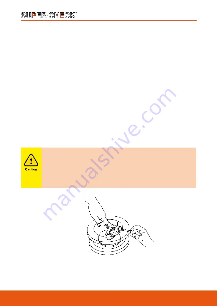
Important see Diagram 5 and caution note below about guarding the spring during disassembly to 
prevent eye damage. Refer to exploded view in Appendix.

5.4 ASSEMBLY SLP SERIES

a) Lay the body (1) down, with ‘downstream’ side of the body facing upward. Lay disc (2) inside the body 

(1). Slide hinge pin (3) into the body through the bushings (6) (where fitted) the spring (5) and disc (2). 
Refer paragraph b) below on energising spring into the body. Reinsert disc into body cavity with shaft 
holes inline with side shaft port. Slide shaft into the body through shaft bearing on one side. Continue 
sliding shaft through disc, disc spring and remaining bushing. Check the disc (2) and bushings for end 
play. If body plate is severely worn it should be replaced.

b) Wind the spring (5) 180° in a clockwise direction. Place the wound spring (5) in position between the 

disc hinge lugs ensuring the long convex side of the spring’s leg is against the disc, the other end must 
be energised against the wall of the valve as per the Diagram 4. Different sizes and classes may have 
different spring configurations. While maintaining pressure on the spring (5), insert the hinge pin (3) 
into the body (1) passing it through the bushings (6) (where required), disc (2) and spring (5) as detailed 
above in paragraph a).

c) Teflon tape the threads of the hinge pin retainer, and screw the hinge pin retainers (8) into the body (1).

After repair, the valve should be retested as per API 598 or applicable standard.

DIAGRAM 5

For SLP and SW series: under no circumstances wind springs to gain a higher or 
lower torsional load. Special high and low torque springs are available for this 
purpose. Before attempting shaft extraction, be sure to press hand over the disc 
spring (see Diagram 5). Failure to do this may result in personal injury due to the 
spring “launching” itself unexpectedly once the shaft is pulled free of it. Always 
wear protective eyewear.

Summary of Contents for SLP

Page 1: ...www australianpipelinevalve com au INSTALLATION OPERATION MAINTENANCE MANUAL WAFER PATTERN CHECK VALVES SLP SW STYLE...

Page 2: ...et Oilfield Products Valves Wellheads Gate Globe Check Valves Forged Steel Plug Valves Lubricated Sleeved Lined Gate Globe Check Valves Cast Steel Diamond Gear Gearboxes Flowturn Gate Globe Check Valv...

Page 3: ...aning 6 2 5 Direction of flow 6 2 6 Horizontal piping 7 2 7 Distance between single flap check valve and butterfly valve 7 2 8 Orientation of single flap wafer check valve to pump discharge 7 8 2 9 Ga...

Page 4: ...lications requirements of the service application RECEIVING INSPECTION AND HANDLING Valves should be inspected upon receipt to ensure Conformance with all purchase order requirements Correct type pres...

Page 5: ...l parts disc stem hinge pin seats gaskets seals etc shall be handled with care avoiding scratches or surface damage b All tools and equipment for handling the internal parts shall be soft coated or el...

Page 6: ...e uniflap checks SLP SERIES retainer type Light and strong Supercheck SLP SW series valves are light so line stress is reduced to a minimum Yet the installed valve assembly is more rigid than an equiv...

Page 7: ...ANSI 150 285 psi 1964 kpa ANSI 300 740 psi 5099 kpa ANSI 600 1480 psi 10197 kpa ANSI 900 2220 psi 15296 kpa ANSI 1500 3705 psi 25527 kpa TABLE E 200 psi 1378 kpa 2 0 I N S T A L L A T I O N ORIENTATI...

Page 8: ...NSTALLATION Remove protective end caps or plugs and inspect valve ends for damage to flange faces Thoroughly clean adjacent piping system to remove any foreign material that could cause damage to seat...

Page 9: ...plate of the Supercheck check valve does not touch the disc of the other valve in the open position For separating other valves such as butterfly valves a spacer spool may be required to stop the disc...

Page 10: ...n caustics are to be used to flush the line additional flushing with clean water is required The valve should be opened and closed after installation to ensure proper operating function With the line...

Page 11: ...have maintenance personnel effect repairs Flange face gasket sealing surfaces should be scraped clean avoid radial marks 5 2 REMOVING VALVE FROM PIPELINE Only one half of the stud bolts need to be rem...

Page 12: ...Place the wound spring 5 in position between the disc hinge lugs ensuring the long convex side of the spring s leg is against the disc the other end must be energised against the wall of the valve as...

Page 13: ...Diagram 5 SLP type shown but guard spring in the same manner and caution note on previous page about guarding spring during disassembly to prevent eye damage Refer to exploded view in Appendix 5 6 AS...

Page 14: ...cording to size class trim RESILIENT O RING SEAT OPTION SLP SW 1 BODY 2 DISC 1 3 HINGE PIN 4 SEAT INTEGRAL 5 SPRING 6 BUSHINGS 2 8 HINGE PIN RETAINERS 9 EYE BOLT SLP STYLE COMPONENTS 1 Integral versio...

Page 15: ...98 d 300 12 18 0 36 Not required per API598 d 0 c Not specified c 3 b Not required per API598 d 350 14 21 0 42 Not required per API598 d 0 c Not specified c 4 b Not required per API598 d 400 16 24 0 4...

Page 16: ...tact us for a prompt response Continuous development of Australian Pipeline Valve products may necessitate changes in the design or manufacture process Australian Pipeline Valve reserves the right to...

Reviews: