background image


14 


5. Operation 

5.1 Power ON/OFF 

Once the unit has been properly installed and the batteries are connected well, simply press On/Off 
switch(located on the button of the case) to turn on the unit. 

5.2 Operation And Display Panel 

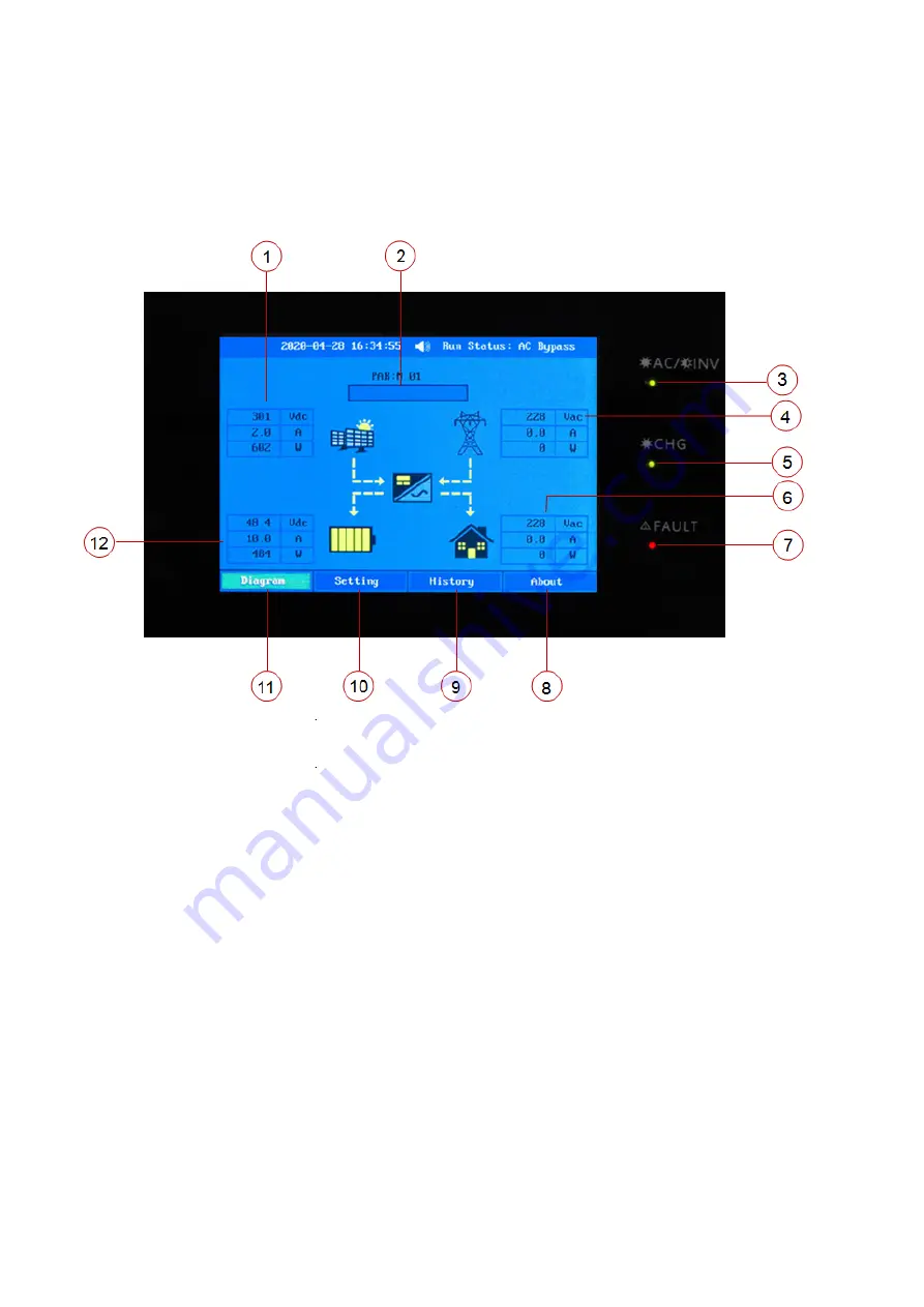
The operation and display panel, shown in below chart, is on the front panel of the inverter. It includes three 
indicators, four function keys and a LCD display, indicating the operating status and input/output power 
information. 


1. PV input information                                           2. Operation information 

3. AC/INV indicator                                                 4. AC Input information 

5. Charging indicator                                               6. AC Output information 

7. Fault indicator                                                      8. About button 

9. History button                                                     10. Setting button 

11. Diagram button                                                   12. Battery information 


PV1/PV2 

Summary of Contents for 8KW

Page 1: ...User Manual 8KW SOLAR INVERTER CHARGER Version 1 0 ...

Page 2: ...l 13 5 Operation 14 5 1 Power ON OFF 14 5 2 Operation And Display Panel 14 5 3 LCD Display Icons 15 5 4 LCD Setting 16 6 Parallel Installation Guide 23 6 1Parallel Operation Cable 23 6 2 Matters Needing Attention In Single phase Parallel Operation 23 6 3 Single phase Parallel Operation Cable Connection 24 6 4 Matters Needing Attention In Three phase Parallel Operation 26 6 5 Three phase Parallel O...

Page 3: ...ion for the battery supply 11 GROUNDING INSTRUCTIONS This inverter charger should be connected to a permanent grounded wiring system Be sure to comply with local requirements and regulation to install this inverter 12 NEVER cause AC output and DC input short circuited Do NOT connect to the mains when DC input short circuits 13 Warning Only qualified service persons are able to service this device ...

Page 4: ...ctures depending on your requirements This inverter can power various appliances in home or office environment including motor type appliances such as tube light fan refrigerator and air conditioners NOTE The following picture is only a schematic diagram of the equipment If the actual chassis does not conform to the schematic due to a structural upgrade it is subject to prior notice Figure 1 Basic...

Page 5: ...rt 4 RS485 port CAN port 5 RS232 port 6 Battery positive 7 Battery negative 8 Parallel port 9 Current sharing port 10 PV1 negative connector 11 PV1 positive connector 12 PV2 negative connector 13 PV2 positive connector 14 WIFI port 15 Power on off switch 16 AC input connector 17 AC output connector Note RS485 CAN communication share the same port so it can t be used at the same time Communication ...

Page 6: ... actual chassis does not conform to the schematic due to a structural upgrade it is subject to prior notice 4 3 Mounting The Unit Consider the following points before selecting where to install 1 Do not mount the inverter on flammable construction materials 2 Mount on a solid surface 3 Install this inverter at eye level in order to allow the LCD display to be read at all times 4 The ambient temper...

Page 7: ...RNING All wiring must be performed by a qualified personnel WARNING It s very important for system safety and efficient operation to use appropriate cable for battery connection To reduce risk of injury please use the proper recommended cable and terminal size as below Recommended battery cable and terminal size Ring terminal Model Typical Amperage Battery capacity Wire Size Cable mm2 Ring Termina...

Page 8: ...crewed to the battery terminals WARNING Shock Hazard Installation must be performed with care due to high battery voltage in series CAUTION Do not place anything between the flat part of the inverter terminal and the ring terminal Otherwise overheating may occur CAUTION Do not apply anti oxidant substance on the terminals before terminals are connected tightly CAUTION Before making the final DC co...

Page 9: ...nnection To reduce risk of injury please use the proper recommended cable size as below Suggested cable requirement for AC wires Model Gauge Torque Value 8KW 8 AWG 1 4 1 6Nm Please follow below steps to implement AC input output connection 1 Before making AC input output connection be sure to protector disconnected first 2 Remove insulation sleeve 10mm for six conductors And shorten phase L and ne...

Page 10: ... PV modules please install separately DC circuit breakers between inverter and PV modules CAUTION It is forbidden for inverter to share the same solar panel group NOTE1 Please use 600Vdc 30A circuit breaker NOTE2 The overvoltage category of the PV input is II Please follow the steps below to implement PV module connection WARNING Because this inverter is non isolated only three types of PV modules...

Page 11: ...assembly process Strip one cable 8 mm on both end sides and be careful NOT to nick conductors Insert striped cable into female terminal and crimp female terminal as shown below Insert assembled cable into female connector housing as shown below Insert striped cable into male terminal and crimp male terminal as shown below Insert assembled cable into male connector housing as shown below ...

Page 12: ...tion cable to negative pole of PV input connector WARNING For safety and efficiency it s very important to use appropriate cables for PV module connection To reduce risk of injury please use the proper cable size as recommended below CAUTION Never directly touch the terminals of inverter It might cause lethal electric shock PV1 Connection PV2 Connection Model Cable mm2 AWG Torque value max 8KW 4 1...

Page 13: ...INPUT 2 Q ty of panels Total Input Power Min in series 4pcs per input Max in series 12pcs per input 4pcs in series x 4pcs 1000W x 4pcs in series 4pcs 1000W 12pcs in series x 12pcs 3000W x 12pcs in series 12pcs 3000W 6pcs in series 6pcs in series 12pcs 3000W 6pcs in series 2 strings x 12pcs 3000W x 6pcs in series 2 strings 12pcs 3000W 8pcs in series 2 strings x 16pcs 4000W x 8pcs in series 2 string...

Page 14: ... reference only 4 9 Wi Fi Connection Optional 1 The device has its own standard WIFI port if users need to monitor the status and information of the device through WIFI they must connect to the WIFI collector 2 Users can download SmartEss WIFI monitoring software from the app store on their phone 3 Inverters come equipped with factory integrated Wi Fi capability which makes it very easy to integra...

Page 15: ...ge Setting the voltage in program 12 Close Open Battery voltage Setting the voltage in program 13 Open Close 4 11 Bluetooth Communication Optional This unit is equipped with a Bluetooth transmitter Download RevoMonitor APP from Google Play Once the APP is download you may connect RevoMonitor APP to your inverter with the pairing password 1234 The communication distance is roughly 6 7 meters Note 1...

Page 16: ...y panel shown in below chart is on the front panel of the inverter It includes three indicators four function keys and a LCD display indicating the operating status and input output power information 1 PV input information 2 Operation information 3 AC INV indicator 4 AC Input information 5 Charging indicator 6 AC Output information 7 Fault indicator 8 About button 9 History button 10 Setting butto...

Page 17: ...current and power information PV input voltage PV input current PV input power information NOTE the information of PV1 and PV2 is automatically switched every 3 seconds Battery voltage current and power information Indicates the DC AC inverter circuit is working Parallel status Explain PAR Parallel mode M Host S Slave 01 Parallel number Grid mode is enable PV1 PV2 Grid ...

Page 18: ...rsion Machine Type This button includes generation event help language working mode input output battery charge PV parallel date and time Grid peak valley and other work state diagram 5 4 LCD Setting After press function button the unit will enter setting mode Set password 1155 Setting Language Work Mode Input Output Battery Charge PV Parallel Date Time Grid Res Other Exit ...

Page 19: ...ame time When solar energy and batteries are insufficient or solar energy is unavailable AC power to the loads and charge the battery at the same time Battery option Battery provides power to the loads as the priority AC provides power to the loads when battery voltage drop to low level warning voltage or setting point and the AC power will charge the battery When the battery is fully charged batt...

Page 20: ...choose this option 4 3 if the BMS communication is connected between the inverter and the lithium battery the display battery icon will display USER Battery 1 Low Vol Disconnect Setting voltage point back to utility source when selecting Solar or Battery setting range 44 0V to 51V Increment of each click is 0 1V 2 Shutdown Vol Setting range is from 42 0V to 48 0V Increment of each click is 0 1V 3 ...

Page 21: ...g point it will automatically switch to utility mode 3 if it only works in battery mode when the load is greater than the current limiting point the inverter will shut down immediately Charge 1 Total Charge 60A default Setting range is from 10A to 120A Increment of each click is 10A 2 AC Charge 30A default Setting range is from 2A 10A to 120A Increment of each click is 10A PV PV CAP Default 3k Acc...

Page 22: ...parallel needs at least three device to do three phase parallel run 3 when three phase parallel make sure that A phase is the host 4 after the parallel parameters are modified the device must be restarted to be effective 5 All inverters must share the same battery pack when paralleling 6 This setting is only available when the inverter is in standby mode Switch off Date Time You can set the local ...

Page 23: ...21 Grid OnGrid enable Res Alternate menu Other Beep Enable default Beep disable mute Other Factory reset disable default Factory reset enable all parameters are restored to their default values ...

Page 24: ...the data in the picture is for reference only Event you can view the running record of the device Help you can view fault and warning codes About LCD display version Inverter control version Mppt control version Machine type ...

Page 25: ...o you can use 60A breaker with only 1 unit and install one breaker at its AC input in each inverter Note 2 Regarding three phase system you can use 4 pole breaker directly and the rating of the breaker WARNING Regarding AC input and output please also follow the same principle should be compatible with the phase current limitation from the phase with maximum units 6 2 Matters Needing Attention In ...

Page 26: ...t If the actual chassis does not conform to the schematic due to a structural upgrade it is subject to prior notice Communication Connection 2 Three inverters in parallel Power Connection NOTE The following picture is only a schematic diagram of the equipment If the actual chassis does not conform to the schematic due to a structural upgrade it is subject to prior notice ...

Page 27: ...al chassis does not conform to the schematic due to a structural upgrade it is subject to prior notice Communication Connection 4 Five inverters in parallel Power Connection NOTE The following picture is only a schematic diagram of the equipment If the actual chassis does not conform to the schematic due to a structural upgrade it is subject to prior notice ...

Page 28: ...forbidden for inverter to share the same solar panel group 4 WARNING Make sure all cables are of the same length Otherwise there will be voltage difference between inverter and battery to cause parallel inverters not working 5 Set the parameters of each inverter independently working mode three phase parallel function and set A B C phase sequence WARNING When working in parallel the working mode o...

Page 29: ...each phase Power Connection NOTE The following picture is only a schematic diagram of the equipment If the actual chassis does not conform to the schematic due to a structural upgrade it is subject to prior notice NOTE P1 A phase P2 B phase P3 C phase Communication Connection ...

Page 30: ... it is subject to prior notice NOTE P1 A phase P2 B phase P3 C phase Communication Connection 3 Four inverters in one phase and one inverter for the other two phases Power Connection NOTE The following picture is only a schematic diagram of the equipment If the actual chassis does not conform to the schematic due to a structural upgrade it is subject to prior notice NOTE P1 A phase P2 B phase P3 C...

Page 31: ...e inverter for the third phase Power Connection NOTE The following picture is only a schematic diagram of the equipment If the actual chassis does not conform to the schematic due to a structural upgrade it is subject to prior notice NOTE P1 A phase P2 B phase P3 C phase Communication Connection ...

Page 32: ... to a structural upgrade it is subject to prior notice NOTE P1 A phase P2 B phase P3 C phase Communication Connection 6 Two inverters in two phases and only one inverter for the remaining phase Power Connection NOTE The following picture is only a schematic diagram of the equipment If the actual chassis does not conform to the schematic due to a structural upgrade it is subject to prior notice NOT...

Page 33: ...he remaining phases Power Connection NOTE The following picture is only a schematic diagram of the equipment If the actual chassis does not conform to the schematic due to a structural upgrade it is subject to prior notice NOTE P1 A phase P2 B phase P3 C phase Communication Connection ...

Page 34: ... start failed 24 PV over temperature 52 Bus voltage is too low 53 Inverter soft start failed 55 Over DC voltage in AC output 57 Current sensor failed 58 Output voltage is too low 8 Warning Code Warning Code Warning Event 01 Fan is locked 02 Over temperature 03 Battery is over charged 04 Low battery 07 Overload 10 Output power derating 08 Over current 15 PV energy is low 16 High AC input 280VAC dur...

Page 35: ...are version inconsistent 72 Current sharing fault 73 Output voltage different 80 CAN fault 81 Host loss 82 Synchronization loss 83 Battery voltage detected different 84 AC input voltage and frequency detected different 85 AC output current unbalance 86 AC output mode setting is different ...

Page 36: ...rect When the unit is turned on internal relay is switched on and off repeatedly LCD display and LED flashing Set Solar First as the priority of output source Change output source priority to utility first Buzzer beeps continuously and red LED is on Fault code 01 Fan fault Replace the fan Fault code 02 Internal temperature of inverter component is over 85 C Check whether the environment around the...

Page 37: ...otection 1 restart the inverter 2 check if L N cables are not Connected reversely in all inverters 3 for parallel system in single phase make sure the sharing are connected in all inverters For supporting three phase system make sure the sharing cables are connected in the inverters in the same phase and disconnected in the inverters in different phase Fault code 71 Firmware version inconsistent 1...

Page 38: ... close please check if all battery cables are the same length and same material type Otherwise please contact your installer to provide SOP to calibrate battery voltage of each inverter 3 If the problem still remains please contact your installer Fault code 84 AC input voltage and frequency detected different Check whether the input voltage and frequency of each inverter are set the same Fault cod...

Page 39: ...tage 270Vac 7Vac Max AC Input Voltage 300Vac Max AC Input Current 60A Nominal Input Frequency 50Hz 60Hz Auto detection Low Loss Frequency 40 1Hz Low Loss Return Frequency 42 1Hz High Loss Frequency 65 1Hz High Loss Return Frequency 63 1Hz Output Short Circuit Protection Line mode AC input fuse Battery mode Electronic Circuits Efficiency Line Mode 95 Rated R load battery full charged Transfer Time ...

Page 40: ...Vdc Low DC Warning Voltage load 20 20 load 50 load 50 44 0Vdc 42 8Vdc 40 4Vdc Low DC Warning Return Voltage load 20 20 load 50 load 50 48 0Vdc 44 8Vdc 42 4Vdc Low DC Cut off Voltage load 20 20 load 50 load 50 44 0Vdc 40 8Vdc 38 4Vdc High DC Cut off Voltage 60Vdc Communication RS232 or RS485 or CAN WIFI option and Bluetooth option Note 1 RS485 CAN communication share the same port so it can t be us...

Page 41: ...Battery 58 4Vdc AGM Gel Battery 56 4Vdc Floating Charging Voltage 54 0Vdc Overcharge Protection 60 0Vdc Charging Algorithm 3 Step Charging Curve Solar Input MODEL 8KW48Vdc Max PV Array Power 4000W 2 Max PV Array Open Circuit Voltage 450Vdc Nominal PV Voltage 360Vdc PV Array MPPT Voltage Range 120Vdc 450Vdc Max Input Current 18A 2 Power Limitation ...

Page 42: ... C 60 C Humidity 5 to 95 Relative Humidity Non condensing Dimension L W H mm 554 420 153 Net Weight kg 18 4 12 Installation Dimension Drawing unit mm NOTE The following picture is only a schematic diagram of the equipment If the actual chassis does not conform to the schematic due to a structural upgrade it is subject to prior notice ...

Page 43: ...614 C0525 00 ...

Reviews: