background image

APsystems ECU-3 V4 Installation/User Manual

25

Local Network Interface

Clearing inverter IDs

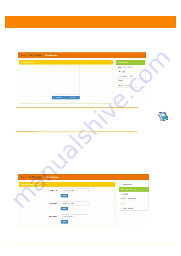
Pressing “Clear ID” deletes ALL of the inverter IDs from the list.

The ID Management page with the existing inverter IDs is displayed.

Figure 36

NOTE:

Combine the above two (2) steps when swapping

out an inverter. Add the new inverter, and Delete the old

one. Remember to follow up with the same process on the

APsystems EMA because the ECU and EMA need to be in

sync with each other.

b) Changing the Date, Time Zone

It is critical for accurate power production reporting that the ECU
is programmed with the correct date, time, and time zone.

1) Select “Administration” at the top of the page.

2) Select “Date, Time, Timezone”.

The Date, Time, Time Zone page is displayed.

Figure 37

3) Adjust the correct date in the “Date Time” field

4) Select the correct time zone from the Time Zone pull down.

Summary of Contents for ECU-3

Page 1: ...Installation User Manual Rev 1 1 All Rights Reserved APsystems ECU 3 V4 Energy Communication Unit ECU...

Page 2: ...nce 9 Step 1 Power on ECU 10 Step 2 ECU time zone setting 12 Step 3 EMA Monitoring 12 Basic Operation 13 Menu Structure 13 Restore the factory set operation 14 Troubleshooting 15 Local Network Interfa...

Page 3: ...d module in your solar installation from any web connected device The APsystems Communicator s integrated http webserver offers the simplest and most flexible network integration of any data logger on...

Page 4: ...nterface and reset Power Connection Port RS232 Serial port Network port USB interface Reset Figure 2 Power Connection Port Power connection port connects power through the power line Figure 3 RS232 Se...

Page 5: ...log in ECU s local page in the case of the absence of the wired LAN and WLAN set up the system and view the system data via Ethernet network port USB Interface USB interface is reserved Reset Press th...

Page 6: ...the APsystems EMA online monitoring application A pre programmed ECU Selecting an Installation Location for the ECU A location that is electrically as close to the array as is possible preferably a de...

Page 7: ...hors installed 130 mm apart The drywall screws and wall anchors are NOT included in the ECU kit Align and slide the ECU onto the mounting screws Figure 7 Best Practice Install and connect the ECU to t...

Page 8: ...LAN cable to the network port on the bottom of the ECU Internet Connection There are three different approaches to connecting the ECU to the Internet Option 1 Direct LAN cable connection 1 Make sure...

Page 9: ...for specific operating instructions Figure 10 NOTE The network cable in the package could be used for the users to connect the ECU with PC directly One side is connected with the ECU and the other si...

Page 10: ...ble into a dedicated standard AC electrical outlet WARNING Make sure to use a dedicated outlet for the ECU Do NOT plug any other devices into the same outlet as the ECU Figure 11 WARNING Do NOT plug t...

Page 11: ...rotocols The ECU needs to have access to the router via a lan IP address The ECU will only search for and obtain a Dynamic Host Configuration Protocol DHCP IP address during its powering up sequence F...

Page 12: ...specifics If however the LCD displays 192 168 131 228 the ECU router connection has not been successful in which case you ll need to check all of the cabling connections and reboot the ECU by removing...

Page 13: ...ill NOT auto sense the inverters see Managing Inverter IDs pg 20 Step 2 ECU time zone setting Enter the IP address shown on the ECU LCD into the internet browser and then open the web page Click Admin...

Page 14: ...tion of the whole system Menu Structure You can access the ECU s menu by pressing and holding the Menu Button on the side of the ECU for 2 seconds MENU Button Figure 16 NOTE The Menu Button will only...

Page 15: ...e turned off Choose Cancel ECU will exit the menu Figure 20 If within one minute without pressing the button again then automatically exit the menu button NOTE The above operation should be done under...

Page 16: ...U could not connect to the APsystems website Check network connectivity to the router You may need to contact your Internet Service Provider or refer to your router documentation for troubleshooting a...

Page 17: ...isplayed Figure 23 Connecting directly to the ECU via wired lan Using a Windows based PC 1 Connect the computer to the ECU using a CAT5 network cable 2 Power up the ECU by connecting the power cable 3...

Page 18: ...using a CAT5 network cable 2 Power up the ECU by connecting the power cable 3 Select the Apple icon in the menu bar to access System Preferences 4 Select Network in the Internet Wireless section of t...

Page 19: ...function on PC 2 Connect to the ECU s Wi Fi named with ECU WIFI_xxxx the xxxx means ECU s last 4 numbers of its ID and connect The first connection have no password 3 Using a standard web browser on y...

Page 20: ...ycle Amount of power that has been generated during the most current day The last time the ECU checked into the central APsystems EMA database Number of Inverters Last Number of Inverters Online Curre...

Page 21: ...ata from the ECU home screen to navigate to the real time data screen The Real Time Data screen is displayed Figure 25 b Trend of system power To view the system power of any period click Power at the...

Page 22: ...al 21 Local Network Interface The Power generation statistics screen is displayed Power generation statistic of current week Figure 27 Power generation statistic of current month Figure 28 Power gener...

Page 23: ...ge The ID Management page is displayed Figure 30 If manually input the inverter IDs 2 Enter each 12 digit inverter ID 3 Once all the ID have been entered press Update And ID updated successfully will...

Page 24: ...Press Update And ID updated successfully will displayed after few seconds Deleting an Existing Inverter ID If the number of inverter ID displayed on the page is more than the actual number of inverte...

Page 25: ...fter few seconds Modify an Existing Inverter ID If the inverter ID displayed on the page is discrepancy with the actual inverters ID installed please modified the wrong inverters ID from Input Inverte...

Page 26: ...te the old one Remember to follow up with the same process on the APsystems EMA because the ECU and EMA need to be in sync with each other b Changing the Date Time Zone It is critical for accurate pow...

Page 27: ...the page 2 Select Language The Language management page is displayed Figure 38 3 Select the language from the Current Language pull down 4 Press Update d Managing the Network Connection The default ne...

Page 28: ...onnection ECU can work in two modes Wlan and Hotspot In Wlan mode ECU can connect to a route by Wi Fi In Hotspot mode ECU can create a hotspot phone and PC can connect to ECU to access local web ECU w...

Page 29: ...SSID it will display an edit box below SSID enter the password into the edit box then click Connect The WLAN Connectivity page is displayed Figure 41 4 If ECU has connected to route it will display t...

Page 30: ...ck WLAN Click Hotspot tab click hotspot switch ECU will change to hotspot mode and reboot automatically 2 Refresh the page modify SSID Channel Safe Type and Password click Save 3 PC and phone can now...

Page 31: ...ote functionality allows you to do the following Set Time Zones Manage Inverter IDs There are additional ECU functions available but the instructions are not outlined in this document If you need to a...

Page 32: ...ely through the ECU setting tab If the time zone is not properly set the solar production data will not post properly on the EMA site Load Inverter IDs Once the ECU has been installed you can access t...

Page 33: ...iguration page is displayed Time Zone Pull Down Field Figure 47 2 Using the Time Zone pull down field select the appropriate time zone 3 Press Send Managing Inverter IDs and Updating the Inverter ID L...

Page 34: ...ion 2 Enter all of the inverter IDs into the Inverter ID Field one per line 3 Press Sent Option 2 Using the Scanning Gun to scan the inverter IDs 1 Select Add in Operation Selection 2 Copy the scanned...

Page 35: ...lies with Canadian ICES 003 Model ECU 3 Version 4 Communication Interface Power Line APsystems Proprietary Integrated Wi Fi 802 11g n Ethernet 10 100M Auto sensing Auto negotiation USB interface Stand...

Page 36: ...should be disposed of separately from the municipal waste stream via designated collection facilities appointed by the government or the local authorities 3 The correct disposal of your old appliance...

Reviews: