2–19
PacketMax 5000 Installation and Operation Manual, 10007678 Rev J
Chapter 2. Base Station Components
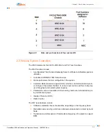
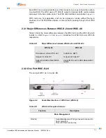
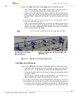
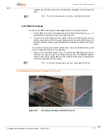
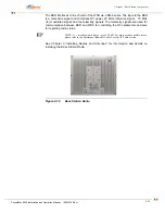
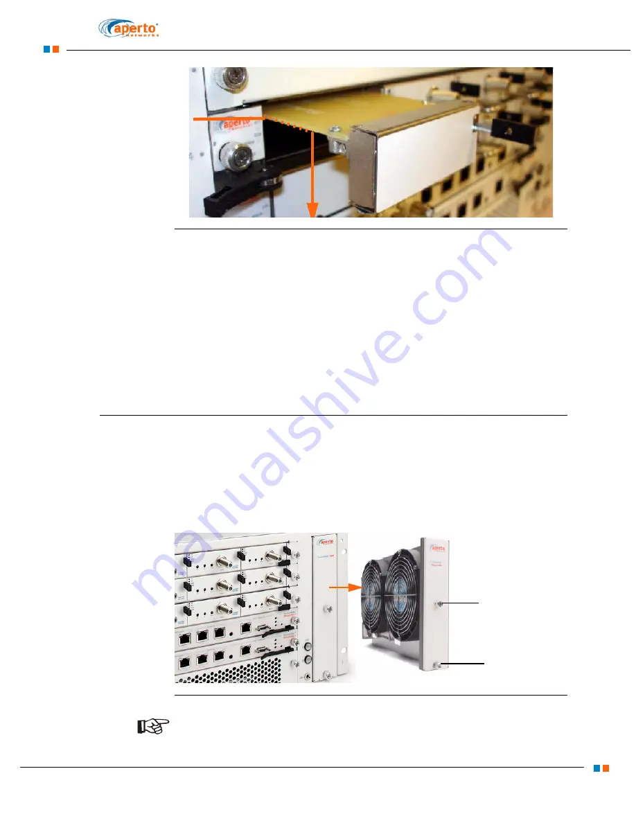
Figure 2-12
Front Panel installed as QWC card
To maintain proper air flow within the chassis and to comply with Electro Magnetic
Interference (EMI) regulations, front panels must be installed on all empty slots.
Hence, PM5000 slots that have no cards installed, need a front panel (P/N: PM 5000-
FRONT PANEL) to be inserted. Each panel has a air baffle on the right hand side.
This air baffle ensures that air flow from the fan units blow only over the inserted
cards. It is critical to have front panels inserted into every “open” slot.
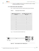
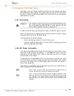
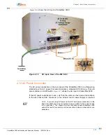
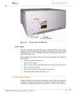
the picture of en empty card inserted in to a base station slot in a PM 5000 four sector
BS, while
2.10 Fan Unit
The PM 5000 uses a hot-swappable modular fan-unit, (P/N: PM5000-FAN-1) that can
be replaced while the system is running.
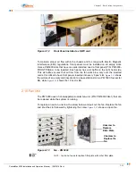
To replace a new fan, unscrew the screw below and pull out the fan. Replace the fan
and shut the slot followed by tightening the screw.
shows an open fan.
Figure 2-13
Fan - PM 5000
NOTE:
You do not need to replace filter plate with other filter plate.
Unscrew to
Replace
Filter Plate
Unscrew to
Replace the
fan
Summary of Contents for PacketMAX 5000
Page 10: ...Preface Preface vi PacketMax 5000 Installation and Operation Manual 10007678 Rev J ...
Page 14: ...Table Of Content TOC 4 PacketMax 5000 Installation and Operation Manual 10007678 Rev J ...
Page 146: ...E 4 PacketMax 5000 Installation and Operation Manual 10007678 Rev J Chapter E Certifications ...
Page 150: ...F 4 PacketMax 5000 Installation and Operation Manual 10007678 Rev J Chapter F Troubleshooting ...

