5–2
PacketMax 5000 Installation and Operation Manual, 10007678 Rev J
Chapter 5. Commissioning the Base Station
5.1 Summary of Configuration of Base Station
To summarize, following are the steps that users have go through in order to configure
the Base Station:
Make sure that Base Station is set up first (Chapter 2,3 and 4).
Refer to network diagram Figure 1-4 on page 1-7 of Chapter 1.
Configure the system by following the sections below
5.2 Establishing an Ethernet Connection with Cat-5
Cable
Before powering on the PM 5000, connect a Cat-5 cable from the Ethernet port on the
PM 5000 to the network where the EMS server is on.
5.3 Establishing a Serial Connection to the Base Sta-
tion
At first, connect your host computer to the PacketMax 5000 using a standard RS-232
serial cable included with the system PM 5000 Base Station. Then, connect the cable
from your host computer’s serial port to the Management RS-232 port on the
PacketMax chassis. Now, power on the base station.
WARNING:
Ensure the PM 5000 is powered down while connecting the host com-
puter. Connecting the base station while the PM 5000 is powered up
can permanently damage the base station or PM 5000 IDU.
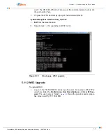
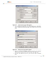
Open a terminal emulation application (for example, HyperTerm) and configure the
connection to support 38,400 baud, no parity, 8 data bits, 1 stop bit, and no flow
control.
Follow the procedure below:
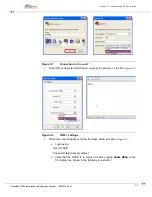
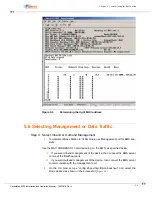
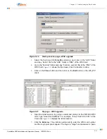
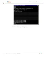
Step 1. Create a new serial connection to the com1.
See
.
Summary of Contents for PacketMAX 5000
Page 10: ...Preface Preface vi PacketMax 5000 Installation and Operation Manual 10007678 Rev J ...
Page 14: ...Table Of Content TOC 4 PacketMax 5000 Installation and Operation Manual 10007678 Rev J ...
Page 146: ...E 4 PacketMax 5000 Installation and Operation Manual 10007678 Rev J Chapter E Certifications ...
Page 150: ...F 4 PacketMax 5000 Installation and Operation Manual 10007678 Rev J Chapter F Troubleshooting ...


