background image


23 

6   How to Use the Reset\Security Pushbutton 

This  chapter  describes  how  to  use  the 

Reset\Security

  pushbutton  to  add  new 

devices into or remove devices from a HomePlug AV logical network (AVLN). 
You can monitor the operation progress and results by observing the Power LED 
status. 

6.1   Forming a HomePlug AV logical network 
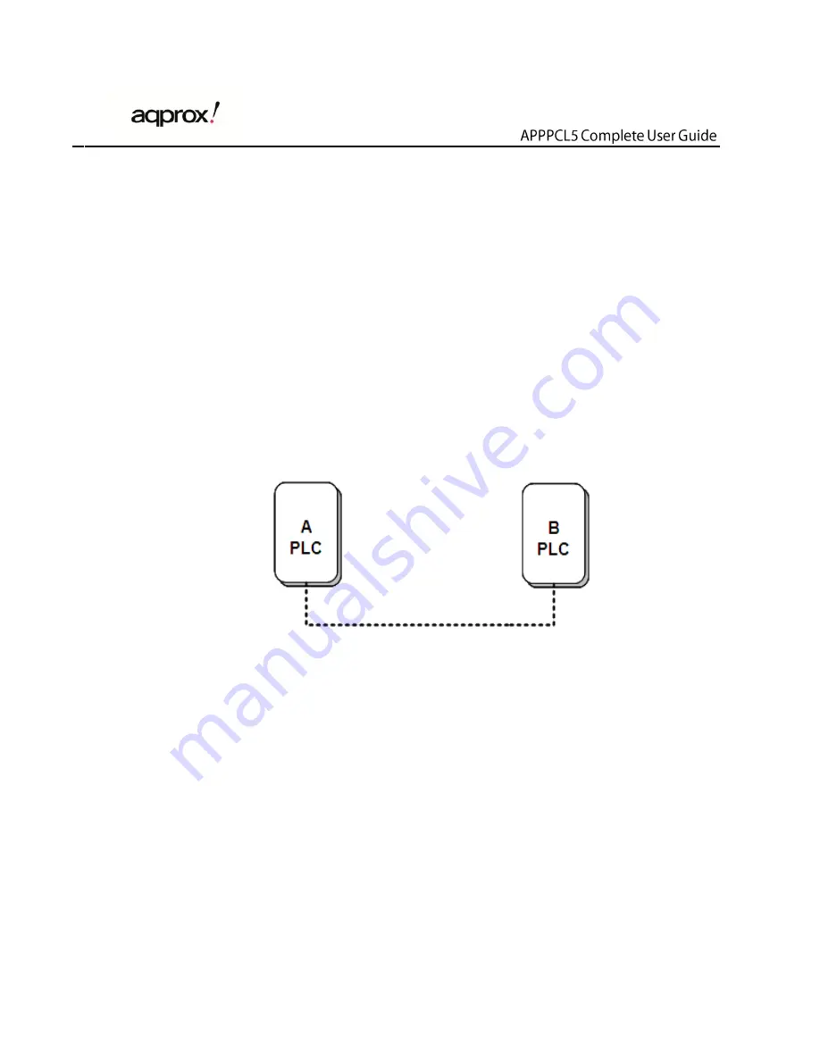
Scenario:   

Devices A and B with different NMK values are connected to the same powerline. 
Users want to use them to form a logical network.   


Figure 16 Form a HomePlugAV network 

Do as follows to form a logical network: 

Step 4 

Press the 

Reset\Security

 pushbutton on device A or B for about 5-8 

seconds. The device will reset and restart with a random NMK. 

Step 5 

Press the 

Reset\Security

 button on device A for less than 3 seconds. 

Step 6 

Within 2 minutes, press the 

Reset\Security

 button on device B for less 

than 3 seconds.   

Step 7 

Wait for connection to complete. 

 
The power indicator on both devices will flash evenly at 1 second intervals until the 
operation  succeeds  or  fails.  If  the  connection  succeeds,  the  Power  and  Data 

Summary of Contents for APPPCL5

Page 1: ...Complete User s Guide appPLC5 ...

Page 2: ...ons 4 3 3 The Adapter s LEDs 4 4 How to Install the Utility 7 5 How to Use the Utility 12 5 1 Main Tab 12 5 2 Privacy Tab 17 5 3 Diagnostics Tab 19 5 4 About Tab 21 6 How to Use the Reset Security Pushbutton 23 6 1 Forming a HomePlug AV logical network 23 6 2 Joining a Network 24 6 3 Leaving a Network 25 7 How to Improve the Transmission Capacity 26 Appendix A Specifications 27 Appendix B Acronyms...

Page 3: ...esidential at home and commercial offices apartments hotels warehouses network applications 1 1 Product Features Without new wiring every power socket becomes a connection node in the household Plug and play to your routers computers and other network devices Provides power save mode In the power save mode the output consumption of the device is less than 0 5W The physical data rate is up to 500Mb...

Page 4: ...ating system Windows 98SE 2000 ME XP 32 64 bit Vista 32 64bit 7 32 64bit CPU Intel Pentium III or better clock rate faster than 2 0GHz recommended RAM At least 128MB Screen resolution Any resolution Free disk space At least 20MB Network interface At least one Fast Ethernet 100 Mbps network card and a Ethernet Cord 1 4 Packing List APPPCL5 x 2 CD ROM x 1 RJ45 Ethernet cable x 2 ...

Page 5: ...the device and the AC power source Only a qualified technician should service this product Opening or removing covers may result in exposure to dangerous voltage points or other risks Do not plug the device into a power strip or surge protector because these devices may consist of filter and impair signal Avoid plugging the device right next to noisy sources such as cell phone charger Halogen ligh...

Page 6: ...s buttons Figure 2 Side panel of the device Reset Security Set the status of the device members or restore the factory default settings Pressing and holding the Button for less than 3 seconds makes the adapter a member of the existing AVLN Pressing and holding the Button for between 5seconds and 8 seconds randomizes the Security value Pressing and holding the Button for between 10 seconds and 15 s...

Page 7: ...ure 3 Top view The following table describes the LEDs on the device LED Color Behavior Description Power Green On System runs normally Blink System is resetting Password synchronization is in progress Adpater is in Power Saving mode flashing evently at 3 second interval System enters the power save mode if ...

Page 8: ...Ethernet connection Data Green Oran ge Re d On The PLC adapter has connected to the powerline network The Data LED color will vary according to the physical rate PHY RATE 40Mbps green 20 PHY RATE 40Mbps orange PHY RATE 20Mbps red Off The PLC adapter does not connect to the powerline network Note When data is being transmitted the Data indicator keeps on but does not blink ...

Page 9: ... is another utility installed please uninstall it and restart your computer Follow the steps below to install the utility No password or CD Key is needed Step 1 Please insert the utility CD into the computer s CD ROM drive Select the APPROX PLC 500 Utility Installation folder and then double click the setup exe The page for installing the utility software is displayed ...

Page 10: ...8 Figure 4 Open the setup wizard Step 2 Click Next to display the following page Figure 5 License agreement Step 3 Select I Agree and click Next to display the following page ...

Page 11: ...9 Figure 6 Selecting the folder Step 4 Click Browse to select the installation folder and then click Next to continue ...

Page 12: ...10 Figure 7 Confirm installation Step 5 Click Next to display the following page ...

Page 13: ...11 Figure 8 Completing the installation Step 6 Click Close to finish the installation ...

Page 14: ...ically connected to the computer when the utility is running The top panel shows the local HomePlugAV devices connected to the network interface card NIC of the computer Click Connect The utility automatically scans the powerline periodically for other HomePlugAV devices connected to it If no local HomePlugAV device is discovered the status bar displays NO HOMEPLUG ADAPTERS DETECTED ...

Page 15: ...layed above the remote device panel Network type Public or Private depends on the network status of the local device Autoscan shows whether the autoscan function is on The following information is displayed for all the devices that appear in the lower panel Device Name This column shows the default device name which may be modified To change the name click Rename or click the name and edit it in t...

Page 16: ...k You can click Enter Password to change it The steps for setting the password of the device required when creating a private network are as follows Step 1 Click the device name to select the device in the lower panel Step 2 Click Enter Password A dialog box appears showing the device name and password Figure 11 ...

Page 17: ...oviding suggestions to solve the common problems This process might take a few seconds to get completed Add This button is used to add a remote device to the existing network by entering the device password of the device A dialog box appears Figure 12 You can enter a device name and the password If the device is found and the password is entered correctly a confirmation box appears If a device is ...

Page 18: ...the password and add the device to the network If the device is not located a warning message appears Scan This button is used to perform an immediate search for HomePlugAV devices connected to the powerline network By default the utility automatically scans every a few seconds and updates the displayed information ...

Page 19: ...ect the device included in the network See Figure 13 Figure 13 Privacy tab All HomePlugAV devices are loaded using a default logical network network name which is normally HomePlugAV In the Privacy screen you can modify a private network by changing the network names and the passwords of the devices ...

Page 20: ...or to this are no longer present in the new network effectively making the local devices not to communicate to the devices which are in the old logical network Click Set Local Device Only the devices previously set up with the same logical network same network name appears in the device list Set All Devices This button is used to change the logical network of all devices that appear in the main pa...

Page 21: ...through HomePlug on the powerline network It includes the following Operating system platform version Host network name User name MAC address of all NICs Network interface card connected to the host Identify versions of all driver DLLs and libraries used NDIS and optionally HomePlug chipset manufacturer name Turbo Only devices MAC firmware version Turbo Only devices MAC addresses of all devices co...

Page 22: ...twork are listed Devices that are active on the current logical network show a transfer rate in the rate column Devices on other networks or devices that no longer exist are shown with a in the rate column The following remote device information is available from the diagnostics screen Device alias name MAC address Password Device last known rate Device last known network name HomePlug chipset man...

Page 23: ...call Click Delete to delete the devices which are no longer part of the network A dialog window pops up with a confirmation message if the user wants to delete a device whose password has been entered 5 4 About Tab The About screen shows the software version and provides a html link to a website such as http www approx es Clicking the web address you can visit the web site Figure 15 About tab ...

Page 24: ...22 Preferences The lower part of the panel displays options for turning the autoscan function on or off ...

Page 25: ...nt to use them to form a logical network Figure 16 Form a HomePlugAV network Do as follows to form a logical network Step 4 Press the Reset Security pushbutton on device A or B for about 5 8 seconds The device will reset and restart with a random NMK Step 5 Press the Reset Security button on device A for less than 3 seconds Step 6 Within 2 minutes press the Reset Security button on device B for le...

Page 26: ...ork N using the Reset Security button Step 8 Press the Reset Security pushbutton on device C the joiner for about 5 8 seconds The device will reset and restart with a random NMK Step 9 Press the Reset Security button on device C the joiner for less than 3 seconds Step 10 Within 30 seconds press the Reset Security button on device A or device B for less than 3 seconds Step 11 Wait for connection to...

Page 27: ...ollows to remove device C from network N Step 12 Press the Reset Security pushbutton on device C the leaver for about 5 8 seconds The device will reset and restart with a random NMK Step 13 Wait for reset to complete The Power indicator on device C momentarily extinguishes during reset blinks during restart and then illuminates steadily After device C is removed from its existing network users can...

Page 28: ...ith the following correct rules because it can significantly improve the transmission capacity of the network For the PLC device without female socket it is recommended to plug the device directly into a wall socket not to power stripe Figure 19 Connecting the PLC device without the female socket ...

Page 29: ...Modulation Band 2 68MHz Modulation Schemes Supports OFDM 4096 1024 256 64 16 8 QAM QPSK BPSK and ROBO Encryption 128 AES LED s Power Ethernet Data Push Button Reset Restore the factory default settings Security Set the network password automatically Consumption 3W Operating Temperature 0ºC to 40ºC Storage Temperature 20ºC to 70ºC Operating Humidity 10 to 90 non condensing Storage Humidity 5 to 95 ...

Page 30: ...28 Input Rating 100 240 VAC 50 60Hz Certifications CE UL FCC Part 15 Class B Green Standard RoHS Physical Dimension L W H 69mm 58mm 31mm Weight 80g ...

Page 31: ...oidance DAK Device Access Key DM Device Manager IGMP Internet Group Management Protocol NEK Network Encryption Key NID Network ID Identification NMK Network Membership Key PLC Powerline Communication PIB Parameter Information Block STA Station a STA in the network with a connection to the powerline and being able to source or sink traffic TDMA Time Division Multiple Access TEI Terminal Equipment I...

Reviews: