10
2.5 ALARM In/Out
10.ALM-IN 1
9.ALM-IN 2
8.ALM-IN 3
7.ALM-IN 4
6.ALM-OUT NO
3.GND
5.ALM-OUT NC
4.ALM-OUT COM
2.RS-485 D
1.RS-485 D+
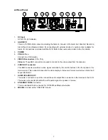
1.
RS-485 D+/ RS-485 D- :
The RS-485 communication ports function as connectors when two
or more units are serially connected to an external control device.
2.
GND:
Ground Contact.
3.
ALM-OUT COM:
This is an alarm output trigger. Connect this to external devices such as
buzzers or lights. (
5V
0V(Active)
)
4.
ALM-OUT NC:
This is an alarm output trigger. Connect this to external devices such as
buzzers or lights. (
5V
0V(Active)
)
5.
ALM-OUT NO:
This is an alarm output trigger. Connect this to external devices such as
buzzers or lights. (
5V
0V(Active)
)
6.
ALM-IN 4:
This is an alarm input that can be programmed in the menu system to Normally
Open or Normally Closed. (
5V
0V(Active)
)
7.
ALM-IN 3:
This is an alarm input that can be programmed in the menu system to Normally
Open or Normally Closed. (
5V
0V(Active)
)
8.
ALM-IN 2:
This is an alarm input that can be programmed in the menu system to Normally
Open or Normally Closed. (
5V
0V(Active)
)
9.
ALM-IN 1:
This is an alarm input that can be programmed in the menu system to Normally
Open or Normally Closed. (
5V
0V(Active)
)
Summary of Contents for DVR-3254S
Page 2: ......
Page 74: ...72 Figure 7 Verifying IP Address of DVR RMN0400372 V1 2 ...

