background image

PAD INSTALLATION 

Pad Location 

Driveway 

Direction of Opening 

12” 

24” 

24” 

5” 

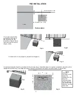
The required depth of the 
pad will vary from site to 
site. Normally, the pad 
should be at least 4” above 
the surface and 18” below 
(Figure A & B). 

Fig. A 

Fig. B 

In harder soil or rock, pilings may be preferred (Figure C). 

Conduit requirements should be considered in the planning stage. If electrical power is required, a separate conduit should be 
installed for electrical only. A certified electrician should be consulted for the proper conduit material  (Figure D & E). 

Fig. C 

Fig. D 

AREA FOR CONDUIT 

ENTRY 

3” 

14” 

5” 

Fig. E 

Note: 

Allow the 
concrete to cure 
as per the 
directions on the 
bag. The 
mounting holes 
for the operator 
should be drilled 
after the concrete 
has cured. 

Pad Location 

Summary of Contents for 7100UL

Page 1: ...Model 7100UL INSTALLATION MANUAL 10 04 00 Gate Operators Inc Residential Medium Duty Commercial Slide Gate Operator...

Page 2: ...5 Pad Installation 6 Operator Installation 7 Chain Bracket Installation 8 Chain Chain Bolt Installation 9 Chain Magnets Installation 10 Quick Release Operation 11 Control Board Connections 12 Control...

Page 3: ...TOMATIC GATE sign should be clearly visible from both sides of the gate Always insure that the gate has closed securely before leaving area Arrange with local fire and law enforcement for emergency ac...

Page 4: ...vide up to 200 operations in the event of power outages The battery may be recharged with a trickle charger or by solar energy eliminating the need for costly trenching to remote entrances If a trickl...

Page 5: ...e the general location of the operator chian brackets and solar panel if used 1 Is there a suitable location for the operator 2 Can the solar panel if used be mounted in an unobstructed area facing so...

Page 6: ...Wraps 4 each 404 1 5 Amp Automatic Battery Charger optional 40 Link Master Chain Links 2 each 7100UL Operator 5 16 Washers Lock Nuts Nuts 8 each 5 16 X 2 5 16 U Bolts 4 each 201 208 5 Watt Solar Pane...

Page 7: ...red Figure C Conduit requirements should be considered in the planning stage If electrical power is required a separate conduit should be installed for electrical only A certified electrician should b...

Page 8: ...chassis The holes should be drilled with a 1 2 concrete drill bit STEP 1 Set the operator on the pad as shown Align the sprockets 3 to 5 inches from the inside surface of the gate STEP 2 Mark the four...

Page 9: ...each end of the gate as shown Do not tighten at this time STEP 2 Align the left chain bracket slot with the top teeth of the idler sprocket Idler Sprocket Main Sprocket STEP 3 Align the right chain b...

Page 10: ...nds of the gate STEP 2 Attach the chain to the chain bolt using the master chain link Note A chain breaking tool may be required to reduce the chain to the proper length Chain Path Fig A Fig B TIP If...

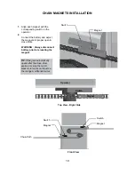
Page 11: ...per open close limits WARNING Always disconnect battery prior to relocating the magnet Chain Path Switch Magnet Switch Magnet Operator Top View Right Side Front View Switch Magnet Switch Magnet 10 1 2...

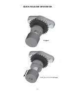
Page 12: ...QUICK RELEASE OPERATION Engaged Engaged Pull turn 1 2 inch to disengage 11...

Page 13: ...ng close cycle 4 RED Motor Negative during open cycle Positive during close cycle 5 GREEN Ground Limit Switch Common 6 NOT USED 7 BLACK Ground Battery Negative 8 RED Battery Positive 12 VDC 8 6 4 2 7...

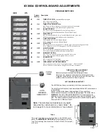
Page 14: ...TELLIGENT ACTUATOR ENABLE ON Controller is connected to Intelligent actuator 816E 816EX OFF Controller is connected to slide gate or other type of actuator TIMER TO CLOSE ADJUSTMENT When Switch 1 is O...

Page 15: ...ller is initially installed it must be put into learn mode The gate should be fully opened and closed 3 5 times and partially opened and closed 3 5 times to allow the controller to adjust to the weigh...

Page 16: ...GND INP 12V black yellow red GND INP 12V GND INP 12V white silver common n o white gold 4 3 2 1 white black red white Do not confuse the receiver code switches with the red program switches on the gat...

Page 17: ...tion to improper power source or if damage was caused by fire flood or lightning The manufacturer will not be responsible for any labor charges incurred in the removal or replacement of defective part...

Reviews: