background image

APC-3X14 User Manual   

89 

Multiple Monitors 

Multiple Monitors supports from two to six touch screen displays for one system. The PenMount 

drivers for Windows 2000/XP support Multiple Monitors. This function supports from two to six touch 

screen displays for one system. Each monitor requires its own PenMount touch screen control board, 

either installed inside the display or in a central unit. The PenMount control boards must be connected 

to the computer COM ports via the RS-232 interface. Driver installation procedures are the same as 

for a single monitor. Multiple Monitors supports the following modes: 


Windows Extend Monitor Function 

Matrox DualHead Multi-Screen Function 

nVidia nView Function 


NOTE: 

The Multiple Monitors function is for use with multiple displays only. Do not use this function if 

you have only one touch screen display. Please note once you turn on this function the Rotating 

function is disabled. 


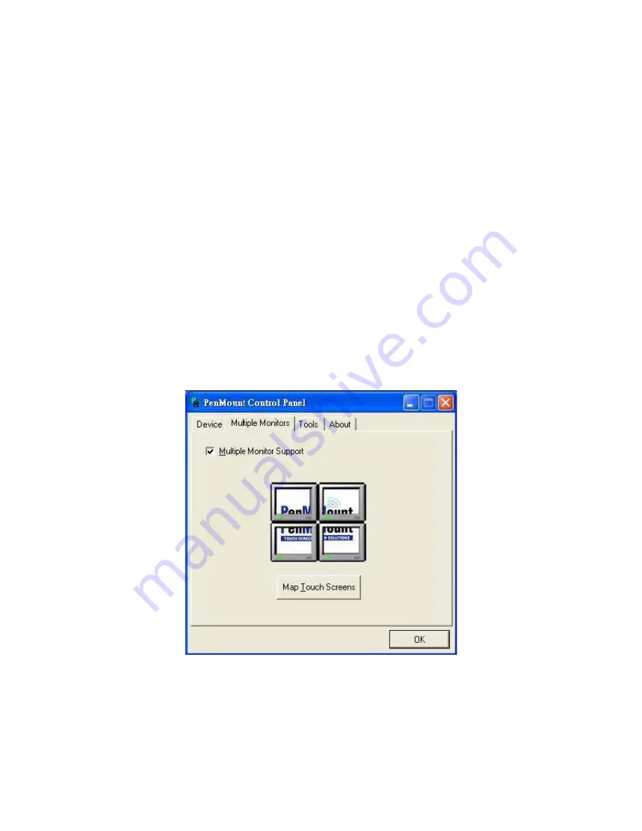
Enable the multiple display function as follows: 

1. Check the “

Multiple Monitor Support” 

box; then click “

Map Touch Screens” 

to assign touch 

controllers to displays. 


Summary of Contents for APC-3514

Page 1: ... Date Revision July 2011 V1 0 2011 Aplex Technology Inc All Rights Reserved Published in Taiwan Aplex Technology Inc 15F 1 No 186 Jian Yi Road Zhonghe District New Taipei City 235 Taiwan Tel 886 2 82262881 Fax 886 2 82262883 E mail aplex aplex com tw URL www aplex com tw ...

Page 2: ...perated in a commercial environment Operation of this equipment in a residential area is likely to cause interference in which case the user at his own expense will be required to take whatever measures may be required to correct the interference Disclaimer This information in this document is subject to change without notice In no event shall Aplex Technology Inc be liable for damages of any kind...

Page 3: ...ent your systems from damage Avoid your system from static electricity on all occasions Prevent electric shock Don t touch any components of this card when the card is power on Always disconnect power when the system is not in use Disconnect power when you change any hardware devices For instance when you connect a jumper or install any cards a surge of power may damage the electronic components o...

Page 4: ...ief Description 13 1 6 Panel Mounting 14 Chapter 2 Hardware 2 1 Main Board 15 2 2 Installing the Memory 16 2 3 Installing the Jumpers 17 2 4 Installing the Connectors 21 Chapter 3 BIOS Setup 3 1 Entering Setup 32 3 2 BIOS setup program 33 3 3 BIOS menu screen 35 Chapter 4 Installation of Drivers 4 1 Intel Chipset Software Installation Utility 62 4 2 VGA Driver Installation 66 4 3 LAN Driver Instal...

Page 5: ...ation for 6000 Boards 79 Figures Figure 1 1 APC 3514 Dimensions 8 Figure 1 2 APC 3714 Dimensions 9 Figure 1 3 APC 3914 Dimensions 10 Figure 1 4 Front View 13 Figure 1 5 Rear View 13 Figure 1 6 Panel Mounting 14 Figure 2 1 Mainboard Overview 15 Figure 5 1 Birdeye s View of Control Board 78 Appendix A Watchdog Timer 94 Watchdog Function 95 ...

Page 6: ... Line out 1 x 3 pin DC Power Input Terminal Block Standard I O 4 x USB 2 0 ports 2 x RJ 45 ports GbE 2 x COM ports RS 232 1 x PS 2 Keyboard 1 x PS 2 Mouse 1 x VGA port 1 x Audio MIC Line in Line out 1 x 3 pin DC Power Input Terminal Block Standard I O 4 x USB 2 0 ports 2 x RJ 45 ports GbE 2 x COM ports RS 232 1 x PS 2 Keyboard 1 x PS 2 Mouse 1 x VGA port 1 x Audio MIC Line in Line out 1 x 3 pin DC...

Page 7: ...APC 3X14 User Manual 7 Relative Humidity 10 90 40 non condensing Certificate CE FCC Class A ...

Page 8: ...APC 3X14 User Manual 8 1 2 Dimensions Figure 1 1 Dimensions of the APC 3514 ...

Page 9: ...APC 3X14 User Manual 9 Figure 1 2 Dimensions of the APC 3714 ...

Page 10: ...APC 3X14 User Manual 10 Figure 1 3 Dimensions of the APC 3914 ...

Page 11: ...he bracket with the four screws as shown by the arrows in the picture Now slide the HDD into the bracket as shown in the picture After that connect the HDD to the SATA means of the cable making sure the red stripe of the cable is connected to the connector of the HDD Get the four screws as circled tightened to secure the HDD As shown in the picture ...

Page 12: ...ces the slot When both parts that are interfaced together come into the right contact slightly push the addon into the rail of the slot This shows the addon is already completely connected After sliding the addon into the PCI expansion slot get the two screws as circled tightened to finish the connection Close the chassis in the same way as it was opened Just tighten the screws as circled and the ...

Page 13: ...50 cd m 19 inch luminance of 350 cd m TFT LCD It is powered by an Intel Atom N270 1 6 GHz processor The industrial panel PC also features one PCI expansion slot two COM ports four USB 2 0 ports one 2 5 HDD a wide range DC 11 32V power input etc It is ideal for use as a PC based controller for industrial automation and factory automation applications Figure 1 4 Front View of APC 3X14 Figure 1 5 Rea...

Page 14: ...714 3914 The APC 3514 3714 3914 panel PC is designed to be panel mounted as shown in Figure 1 6 just carefully place the unit through the hole and tighten the given 8 screws from the rear to secure the mounting Figure 1 6 Panel mounting of the APC 3514 3714 3914 ...

Page 15: ...APC 3X14 User Manual 15 Chapter 2 Hardware 2 1 Mainboard overview Figure 2 1 Mainboard Overview ...

Page 16: ... on a DDR DIMM socket The following figure illustrates the location of the sockets 200 Pin DDR2 SO DIMM sockets Channel Socket Channel A SO DIMM_A1 2 2 1 Memory Configurations You may install 64 MB 128 MB 256 MB 512 MB and up to 2 GB unbuffered ECC or non ECC DDR SO DIMMs into the SO DIMM sockets using the memory configurations in this section 2 2 2 Installing a DIMM Make sure to unplug the power ...

Page 17: ...t get damaged when it flips out with extra force 2 Remove the SO DIMM from the socket 2 3 Installing the Jumpers 1 Clear RTC RAM CLRTC This jumper allows you to clear the Real Time Clock RTC RAM in CMOS You can clear the CMOS memory of date time and system setup parameters by erasing the CMOS RTC RAM data The onboard button cell battery powers the RAM data in CMOS which include system setup inform...

Page 18: ...the system so the BIOS can automatically reset parameter settings to default values 2 COM1 RI 12V and 5V Power Select JCOMPWR1 JCOMPWR2 This jumper allows you to select COM1 RI 5V and 12V power Set JCOMPWR1 to pins 1 3 and JCOMPWR2 to pins 1 3 to select 5V power And set JCOMPWR1 to pins 3 5 and JCOMPWR2 to pins 1 3 to select 12V power Then set JCOMPWR2 to pins 3 5 and JCOMPWR1 to open for RI selec...

Page 19: ...and JCOMPWR2 to pins 2 4 to select 12V power Then set JCOMPWR2 to pins 4 6 and JCOMPWR1 to open for RI selection 4 COM3 RI 12V and 5V Power Select JCOMPWR3 JCOMPWR4 This jumper allows you to select COM3 RI 5V and 12V power Set JCOMPWR3 to pins 1 3 and JCOMPWR4 to pins 1 3 to select 5V power And set JCOMPWR3 to pins 3 5 and JCOMPWR4 to pins 1 3 to select 12V power Then set JCOMPWR4 to pins 3 5 and ...

Page 20: ...stem power LED lights up when you turn on the system power and blinks when the system is in sleep mode 1 ATX Power Button Soft off Button 2 pin PWRSW This connector is for the system power button Pressing the power button turns the system on or puts the system in sleep or soft off mode depending on the BIOS settings Pressing the power switch for more than four seconds while the system is ON turns ...

Page 21: ...s for a PS 2 mouse 2 Serial connector This 9 pin COM1 port is for serial devices 3 DVI connector for APC 3264 only herein ignore this for APC 3514 3714 3914 4 5 LAN RJ 45 port This port allows Gigabit connection to a Local Area Network LAN through a network hub Refer to the table below for the LAN port LED indications ...

Page 22: ...0 USB 2 0 ports 1 and 2 These two 4 pin Universal Serial Bus USB ports are available for connecting USB 2 0 devices 11 VGA port This 15 pin VGA port connects to a VGA monitor 12 Serial connector This 9 pin COM2 port is for serial devices 13 PS 2 keyboard port purple This port is for a PS 2 keyboard 2 4 2 Internal connectors 1 Front panel audio connector 10 pin AAFP1 This connector is for a chassis...

Page 23: ...APC 3X14 User Manual 23 It is recommended that you connect a high definition front panel audio module to this connector to avail of the motherboard s high definition audio capability ...

Page 24: ... pin CHA_FAN The fan connectors support cooling fans of 350mA 740mA 8 88W max or a total of 1A 2 22A 26 64W max at 12V Connect the fan cables to the fan connectors on the motherboard making sure that the black wire of each cable matches the ground pin of the connector Do not forget to connect the fan cables to the fan connectors Insufficient air flow inside the system may damage the motherboard co...

Page 25: ...ector and the other end to the S PDIF module The S PDIF out module is purchased separately 5 USB connectors 10 1 pin USB45 This connector is for USB 2 0 ports Connect the optional USB module cable to any of these connectors then install the module to a slot opening at the back of the system chassis These USB connectors comply with USB 2 0 specification that supports up to 480 Mbps connection speed...

Page 26: ... then select one of the following modes to configure your hard disk drive s Cable Select Mode use this mode to select the operating mode by cable connectors No of drives Drive type Drive jumper Cable connector 1 With OS Cable select black 2 With OS black Without OS gray Jumper Select Mode use this mode to select the operating mode by hard disk drive jumper No of drives Drive type Drive jumper Cabl...

Page 27: ... power supply plugs The power supply plugs are designed to fit these connectors in only one orientation Find the proper orientation and push down firmly until the connectors completely fit 1 Use of a PSU with a higher power output is recommended when configuring a system with more power consuming devices The system may become unstable or may not boot up if the power is inadequate 1 Make sure that ...

Page 28: ...e of hearing to a level suitable for driving loudspeakers and is the final stage in a typical audio playback chain 10 SPI Connector 7 pin SPI_JP1 It is a point to point interface standard allows network equipment designers to develop an array of next generation multi service switches and routers to support multi service traffic with aggregate bandwidths up to OC 192 10 Gb s and beyond enabling the...

Page 29: ...APC 3X14 User Manual 29 11 LCD Inverter Connector 5 pin JBKL ...

Page 30: ...APC 3X14 User Manual 30 12 Digital IO Connector 12 pin JDIO 13 LVDS Connector 40 pin JLVDS 1 Support 18bit x 2CH LVDS ...

Page 31: ...APC 3X14 User Manual 31 1 Support 24bit x 2CH LVDS ...

Page 32: ...c Select the 3 1 2 Floppy Drive icon d Click File from the menu then select Format A Format 3 1 2 Floppy Disk window appears e Select Create an MS DOS startup disk from the format options field then click Start Windows 2000 environment To create a set of boot disks for Windows 2000 a Insert a formatted high density 1 44 MB floppy disk into the drive b Insert the Windows 2000 CD to the optical driv...

Page 33: ... with its test routines If you wish to enter Setup after POST restart the system by pressing Ctrl Alt Delete or by pressing the reset button on the system chassis You can also restart by turning the system off and then back on Do this last option only if the first two failed The Setup program is designed to make it as easy to use as possible Being a menu driven program it lets you scroll through t...

Page 34: ...ain fields This pointer indicates that you can display a sub menu from this field A sub menu contains additional options for a field parameter To display a sub menu move the highlight to the field and press Enter The sub menu appears Use the legend keys to enter values and move from field to field within a sub menu as you would within a menu Use the Esc key to return to the main menu Take some tim...

Page 35: ...wing screen appears The BIOS menu screen displays the items that allow you to make changes to the system configuration To access the menu items press the up down right left arrow key on the keyboard until the desired item is highlighted then press Enter to open the specific menu ...

Page 36: ...econd based on the 24 hour clock 3 3 1 3 IDE Channel 0 1 Master Slave 1 IDE HDD Auto Detection Press Enter to select this option for automatic device detection 1 IDE Device Setup Auto Automatically detects IDE devices during POST None Select this when no IDE device is used The system will skip the auto detection setup to make system start up faster Manual User can manually input the correct settin...

Page 37: ...ced Graphics Adapter Video Graphics Array For EGA VGA SVGA or PGA monitor adapters 1 CGA 40 Color Graphics Adapter power up in 40 column mode 1 CGA 80 Color Graphics Adapter power up in 80 column mode 1 MONO Monochrome adapter includes high resolution monochrome adapters 3 3 1 5 Halt On Sets the system to halt on errors according to the system functions specified in each option Configuration optio...

Page 38: ...es item from the Initial Setup Screen menu It allows the user to configure the RX945G according to his particular requirements Below are some major items that are provided in the Advanced BIOS Features screen A quick booting function is provided for your convenience Simply enable the Quick Booting item to save yourself valuable time ...

Page 39: ...al Monitor should be activated in automatic mode after the system boots For example with the default value of 16 Minutes the BIOS activates the Thermal Monitor in automatic mode 16 minutes after the system starts booting up 1 Limit CPUID MaxVal Set Limit CPUID MaxVa1 to 3 This should be disabled for WinXP 1 C1E Function CPU C1E function select 1 Execute Disable Bit When disabled forces the XD feat...

Page 40: ...boot priority list 3 3 2 2 Virus Warning Enables or disables the virus warning Item Description Enable Activates automatically when the system boots up causing a warning message to appear when anything attempts to access the boot sector or hard disk partition table Disable No warning message will appear when anything attempts to access the boot sector or hard disk partition table 3 3 2 3 CPU L1 L2...

Page 41: ... 100 Device USB FDD USB Floppy Device USB ZIP USB ZIP Device USB CDROM USB CDROM Device USB HDD USB Hard Disk Device Legacy LAN Network Device Disabled Disabled any boot device 3 3 2 7 Boot Other Device Use this to boot another device The options are Enabled and Disabled 3 3 2 8 Boot Up NumLock Status Sets the boot up Num Lock status The options are On and Off Item Description On Enable NumLock Of...

Page 42: ...ly valid for multiprocessor motherboards as it specifies the version of the Multiprocessor Specification MPS that the motherboard will use The MPS is a specification by which PC manufacturers design and build Intel architecture systems with two or more processors MPS 1 1 was the original specification MPS version 1 4 adds extended configuration tables for improved support of multiple PCI bus confi...

Page 43: ...ntrols the latency between the DDR SDRAM active command and the read write command 3 3 3 4 DRAM RAS Precharge Controls the idle clocks after issuing a precharge command to the DDRSDRAM 3 3 3 5 Precharge delay tRAS Precharge Delay This setting controls the precharge delay which determines the timing delay for DRAM precharge 3 3 3 6 System Memory Frequency Allow to choose different frequency of memo...

Page 44: ...e this setting This makes memory from 15 MB and up unavailable to the system Expansion cards can only access memory up to 16 MB The default setting is Disabled 3 3 3 10 On Chip Frame Buffer Size The On Chip Frame Buffer Size can be set as 1MB or 8MB This memory is shared with the system memory 3 3 3 11 DVMT Mode Use this field to select the memory to allocate for video memory The choices are Fixed...

Page 45: ...APC 3X14 User Manual 45 3 3 4 Integrated Peripherals ...

Page 46: ...led to activate each channel separately 1 IDE Primary Secondary Master Slave PIO The four IDE PIO fields allow you to set a PIO mode 0 4 for each of the four IDE devices that the onboard IDE interface supports Modes 0 through 4 provide successively increased performance In Auto mode the system automatically determines the best mode for each device 1 IDE Primary Secondary Master Slave UDMA Ultra DM...

Page 47: ...e IDE RAID AHCI Legacy IDE 1 SATA Port Speed Settings 1 PATA IDE Mode 1 SATA Port 3 3 4 2 Onboard Device 1 Azalia Audio Select Select Disabled if you do not want to use Azalia audio Configuration options Auto Disabled 1 Audio Amplifier 1 Amplifier Gain dB 1 Onboard LAN1 Device 1 Onboard LAN2 Device ...

Page 48: ...ttings are 3F8 IRQ4 2F8 IRQ3 3E8 IRQ4 2E8 IRQ3 and Disabled for the on board serial connector 1 PWRON After PWR Fail This item allows you to select if you want to power on the system after power failure The choice Off On Former Sts 3 3 4 4 Onboard Lan1 2 Boot ROM The choices Enable Disable 3 3 4 5 Watch Dog Timer Select This option will determine watch dog timer The choices Disabled 10 20 30 40 Se...

Page 49: ...o use it Even when so equipped if you add a higher performance controller you will need to disable this feature 1 USB 2 0 Controller Enable the USB 2 0 controller 1 USB Keyboard Support Select Enabled if your system contains a Universal Serial Bus USB controller and you have a USB keyboard 1 USB Mouse Support Select an address and corresponding interrupt for the first and second serial ports ...

Page 50: ...rity Chip Configuration 3 3 5 1 TPM Support The choices are Enabled and Disabled 3 3 5 2 TPM Current Status This item shows you the current TPM status 3 3 5 3 TPM Status The choices are No Change Clear Enable Activate Deactivate Disable ...

Page 51: ... VGABIOS if S3 Resume Select Auto to run VGA BIOS if S3 resume automatically The Yes enables running VGA BIOS if S3 resume The No disables this function 3 3 6 4 Power Management There are three selections for Power Management and each of them has fixed mode settings Item Description Min Power Saving Minimum power management HDD Power Down 15 Min Max Power Saving Maximum power management HDD Power ...

Page 52: ...re from 1 min to 1 hr except for HDD Power Down which ranges from 1 min to 15 min and disable 3 3 6 8 Soft Off by PWR BTTN If you choose Instant Off then pushing the ATX soft power switch but ton once will switch the system to system off power mode You can choose Delay 4 sec If you do then pushing the button for more than 4 seconds will turn off the system whereas pushing the button momentarily fo...

Page 53: ...3 Resources Controlled By The commands here are Auto ESCD or Manual Choosing Manual requires you to choose resources from the following sub menu Auto ESCD automatically configures all of the boot and Plug and Play devices but you must be using Windows 95 or above 3 3 7 4 PCI VGA Palette Snoop This is set to Disabled by default 3 3 7 5 Maximum Payload Size This allows you to set the maximum TLP pay...

Page 54: ... Current CPU1 Temperature This item shows you the current CPU temperature 3 3 8 5 CPU Fan Speed This item shows you the current CPU fan speed 3 3 8 6 System Fan Speed This item shows you the current system fan speed 3 3 8 7 Vcore This item shows you the current Vcore voltage value 3 3 8 8 12V This item shows you the current 12V voltage value 3 3 8 9 5V This item shows you the current 5V voltage va...

Page 55: ...sabled 3 3 9 2 Spread Spectrum This setting allows you to reduce EMI by modulating the signals the CPU generates so that the spikes are reduced to flatter curves This is achieved by varying the frequency slightly so that the signal does not use any particular frequency for more than a moment The choices are Disabled and Enabled 3 3 9 3 CPU Host SRC PCI Clock The choice 100 ...

Page 56: ...0 Load Optimized Defaults Use this menu to load the BIOS default values for the minimal stable performance for your system to operate Press Y to load the BIOS default values for the most stable minimal performance system operations ...

Page 57: ...e CMOS is good and this option has been used to change the default password the user is asked for the password stored in the CMOS The screen displays the following message Please Confirm Your Password 1 Type the current password and press Enter 1 After pressing Enter ROM password or the current password user defined you can change the password stored in the CMOS The password must be no longer than...

Page 58: ...MOS is good and this option has been used to change the default password the user is asked for the password stored in the CMOS The screen displays the following message Please Confirm Your Password 1 Type the current password and press Enter 1 After pressing Enter ROM password or the current password user defined you can change the password stored in the CMOS The password must be no longer than ei...

Page 59: ...s Enter the values entered in the setup utili ties will be recorded in the CMOS memory of the chipset The processor will check this every time you turn your system on and compare this to what it finds as it checks the system This record is required for the sys tem to operate ...

Page 60: ...APC 3X14 User Manual 60 3 3 14 Exit Without Saving Selecting this option and pressing Enter lets you exit the setup program without recording any new values or changing old ones ...

Page 61: ...ndows XP The software and drivers are included with the motherboard The contents include Intel Chipset VGA Driver Network Adapter AC 97 Audio Driver Installation Important Note After installing your Windows operating system Windows XP you must install first the Intel Chipset Software Installation Utility before proceeding with the installation of drivers ...

Page 62: ...oftware drivers to enable Plug Play INF support for Intel chipset components Follow the instructions below to complete the installation Under Windows 98SE ME 2000 XP 1 Insert the Aplex product CD that comes with the board 2 Click Intel Chipset software installation Utility 3 When the Welcome screen appears please click Next to Continue ...

Page 63: ...APC 3X14 User Manual 63 4 Click Yes to accept the software license agreement and proceed with the installation process 5 On Readme information screen click Next to continue the installation ...

Page 64: ...APC 3X14 User Manual 64 ...

Page 65: ...APC 3X14 User Manual 65 6 Click Finish The Setup process is now complete ...

Page 66: ...allation To install the VGA Driver follow the steps below to proceed with the installation Step 1 Insert the Aplex product CD That comes with the board Step 2 Click Intel VGA Chipset Step 3 When the Welcome screen appears click Next to continue ...

Page 67: ...APC 3X14 User Manual 67 ...

Page 68: ...APC 3X14 User Manual 68 Step 4 Click Yes to accept the software license agreement and proceed with the installation process Step 5 On Readme information screen click Next to continue the installation ...

Page 69: ...APC 3X14 User Manual 69 Step 6 Setup Progress ...

Page 70: ...APC 3X14 User Manual 70 Setp 7 Click Finish The Setup process is now complete ...

Page 71: ...anual 71 4 3 Intel LAN Drivers installation Follow the steps below to complete the installation of the Intel LAN drivers Step 1 Insert the Aplex product CD That comes with the board Step 2 Click Intel Network Adapter ...

Page 72: ...APC 3X14 User Manual 72 ...

Page 73: ...APC 3X14 User Manual 73 Step 7 Click Finish The Completing the Install Shield Wizard ...

Page 74: ... the Realtek ALC888 codec Driver follow the steps below to proceed with the installation Step 1 Insert the Aplex product CD That comes with the board Step 2 Click Realtek ALC888 Sound system Step 3 Preparing Setup please wait while the install shield Wizard prepares the setup ...

Page 75: ...APC 3X14 User Manual 75 Step 4 When the Welcome screen appears click Next to continue Step 5 Setup status ...

Page 76: ...APC 3X14 User Manual 76 ...

Page 77: ...APC 3X14 User Manual 77 Setp 6 Click Finish The Setup process is now complete ...

Page 78: ... USB interface and specific for 4 5 8 wire touch screens It is designed with USB interface features with multiple devices supporting function PenMount 6300 control board using PenMount 6000 controller that has been designed for those who may like and all in one solution with 10 bit A D converter built in to make the total printed circuit board denser circuit diagram also designed for 12 bit ADC fo...

Page 79: ... you have an older version of the PenMount Windows 2000 XP driver installed in your system please remove it first Follow the steps below to install the PenMount DMC6000 Windows 2000 XP driver 1 Please make sure your PenMount 6000 device had plugged in advance If your device uses RS232 interface please plugged in before the machine is turned on When the system first detects the controller board a s...

Page 80: ...APC 3X14 User Manual 80 3 A License Agreement appears Click I accept and Next ...

Page 81: ...APC 3X14 User Manual 81 4 Ready to Install the Program Click Install 5 Installing ...

Page 82: ...APC 3X14 User Manual 82 6 The Install Shield Wizard Completed appears Click Finish ...

Page 83: ... functions of the PenMount Control Panel are Device Multiple Monitors Tools and About which are explained in the following sections Device In this window you can find out that how many devices be detected on your system Calibrate This function offers two ways to calibrate your touch screen Standard Calibration adjusts most touch screens Advanced Calibration adjusts aging touch screens Standard Cal...

Page 84: ...ration function Use command mode call calibration function this can uses Standard 4 9 16 or 25 points to calibrate E g Please run ms dos prompt or command prompt c Program Files PenMount Universa Driver Dmcctrl exe calibration 0 Standard Calibration Dmcctrl exe calibration 0 Standard Calibration 4 Advanced Calibration 4 9 Advanced Calibration 9 16 Advanced Calibration 16 25 Advanced Calibration 25...

Page 85: ...E The older the touch screen the more Advanced Mode calibration points you need for an accurate calibration Use a stylus during Advanced Calibration for greater accuracy Please follow the step as below 3 Come back to PenMount Control Panel and select Tools then Click Advanced Calibration ...

Page 86: ...APC 3X14 User Manual 86 Select Device to calibrate then you can start to do Advanced Calibration ...

Page 87: ...APC 3X14 User Manual 87 NOTE Recommend to use a stylus during Advanced Calibration for greater accuracy Setting ...

Page 88: ...APC 3X14 User Manual 88 About This panel displays information about the PenMount controller and driver version ...

Page 89: ... to the computer COM ports via the RS 232 interface Driver installation procedures are the same as for a single monitor Multiple Monitors supports the following modes Windows Extend Monitor Function Matrox DualHead Multi Screen Function nVidia nView Function NOTE The Multiple Monitors function is for use with multiple displays only Do not use this function if you have only one touch screen display...

Page 90: ...hed maybe you need to calibrate for each panel and controller NOTES 1 If you used a single VGA output for multiple monitors please do not use the Multiple Monitors function Just follow the regular procedure for calibration on each of your desktop monitors 2 The Rotating function is disabled if you use the Multiple Monitors function 3 If you change the resolution of display or screen address you ha...

Page 91: ...reen Please press S to skip mapping step Tools Draw Tests or demonstrates the PenMount touch screen operation Advanced Calibration Enable Advanced Calibration function Right Button Icon Enable right button function The icon can show on Desktop or System Tray menu bar ...

Page 92: ...of PenMount controller that are plugged to your system PenMount Monitor Menu Icon The PenMount monitor icon PM appears in the menu bar of Windows 2000 XP system when you turn on PenMount Monitor in PenMount Utilities PenMount Monitor has the following function ...

Page 93: ...oftware ATI Display Driver Rotate Function nVidia Display Driver Rotate Function SMI Display Driver Rotate Function Intel 845G GE Display Driver Rotate Function Configuring the Rotate Function 1 Install the rotation software package 2 Choose the rotate function 0 90 180 270 in the 3rd party software The calibration screen appears automatically Touch this point and rotation is mapped NOTE The Rotat...

Page 94: ...APC 3X14 User Manual 94 Appendix A Watch Dog Timer ...

Page 95: ...APC 3X14 User Manual 95 Using the Watchdog Function ...

Page 96: ...APC 3X14 User Manual 96 ...

Reviews: