APC-3X20 User Manual
30
22. LED1:
LED1: LED STATUS. Green LED for Touch Power status.
23. JP1:
(2.0mm Pitch 2x3 Pin Header), COM1 jumper setting, pin 1~6 are used to select
signal out of pin 9 of COM1 port.
JP1 Pin#
Function
Close 1-2
COM1 RI (Ring Indicator) (default)
Close 3-4
COM1 Pin9: DC+5V (option)
Close 5-6
COM1 Pin9: DC+12V (option)
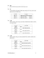
24. S_232
(Switch), COM1 jumper setting, it provides selectable RS232 or RS422 or RS485
serial signal output.
Function
S_232 Pin#
RS232
(Default)
ON:
Pin1, Pin2, Pin3, Pin4
RS422
(option)
OFF:
Pin1, Pin2, Pin3, Pin4
RS485
(option)
OFF:
Pin1, Pin2, Pin3, Pin4
25. S_422:
(Switch), COM1 setting, it provides selectable RS232 or RS422 or RS485 serial
signal output.
Function
S_422 Pin#
RS232
(Default)
OFF:
Pin1, Pin2, Pin3, Pin4, Pin5
RS422
(option)
ON:
Pin1, Pin2, Pin3, Pin4, Pin5
RS485
(option)
ON:
Pin1, Pin2, Pin3, Pin4, Pin5
Summary of Contents for APC-3220
Page 12: ...APC 3X20 User Manual 11 1 3 Dimensions Figure 1 1 Dimensions of APC 3220 ...
Page 13: ...APC 3X20 User Manual 12 Figure 1 2 Dimensions of APC 3920 ...
Page 14: ...APC 3X20 User Manual 13 Figure 1 3 Dimensions of APC 3420 ...
Page 16: ...APC 3X20 User Manual 15 Figure 1 6 Front View of APC 3920 Figure 1 7 Rear View of APC 3920 ...
Page 17: ...APC 3X20 User Manual 16 Figure 1 8 Front View of APC 3420 Figure 1 9 Rear View of APC 3420 ...
Page 22: ...APC 3X20 User Manual 21 units mm Figure 2 1 Mainboard Dimensions ...
Page 72: ...APC 3X20 User Manual 71 Step 4 Click Next to continue Step 5 Click Next to continue ...


