APC-3X20 User Manual
25
Procedures of CMOS clear:
a)
Turn off the system and unplug the power cord from the power outlet.
b)
To clear the CMOS settings, use the jumper cap to close pins 1 and 2 for
about 3 seconds then reinstall the jumper clip back to pins open.
c)
Power on the system again.
d)
When entering the POST screen, press the <ESC> or <DEL> key to enter
CMOS Setup Utility to load optimal defaults.
e)
After the above operations, save changes and exit BIOS Setup.
9. BAT2:
(2.0mm Pitch 1x10 Wafer Pin Header), Smart battery Interface.
Pin#
Signal Name
Pin1
VCC_BAT1
Pin2
VCC_BAT1
Pin3
VCC_BAT1
Pin4
SMB_DAT_SW
Pin5
SMB_SCL_SW
Pin6
BAT1_TEMP
Pin7
Ground
Pin8
Ground
Pin9
Ground
Pin10
SET_BAT1_ON
Function
Specifications
Nominal voltage (3S1P)
11.1~12.6V
Charge voltage
12.6V
Charge current
0.5C
10. BAT_LED:
(2.0mm Pitch 1x4 Wafer Pin Header), The Charge status indicator for BAT2.
Pin1-Pin3: Charge LED status.
Pin2-Pin3: Discharge LED status.
Pin4-Pin3: EC LED status.
Pin#
Signal Name
Pin1
B
Summary of Contents for APC-3220
Page 12: ...APC 3X20 User Manual 11 1 3 Dimensions Figure 1 1 Dimensions of APC 3220 ...
Page 13: ...APC 3X20 User Manual 12 Figure 1 2 Dimensions of APC 3920 ...
Page 14: ...APC 3X20 User Manual 13 Figure 1 3 Dimensions of APC 3420 ...
Page 16: ...APC 3X20 User Manual 15 Figure 1 6 Front View of APC 3920 Figure 1 7 Rear View of APC 3920 ...
Page 17: ...APC 3X20 User Manual 16 Figure 1 8 Front View of APC 3420 Figure 1 9 Rear View of APC 3420 ...
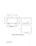
Page 22: ...APC 3X20 User Manual 21 units mm Figure 2 1 Mainboard Dimensions ...
Page 72: ...APC 3X20 User Manual 71 Step 4 Click Next to continue Step 5 Click Next to continue ...


