15
Touch Sensor Method
(automatic way of finding probe Z offset)
a.
After open the "Probe Tip Offset Calibration" window, select "Use touch sensor" option,
shown in Figure 8, then click on "Next". The robot movement is expected and the Z offset
calibration will be automatically measured by touch sensor.
b.
Click on "Finish" and "Yes" to save the changes. Please make sure touch sensor is working
before using this method, otherwise, hardware damage may occur.
4.3.
Take a Picture of DUT
A comb generator is used as a DUT in the following procedures to give the user an idea of taking
a picture of DUT, defining the scan area and the scan height, etc. The “Scan Area Setting” part is
same for all scan types as shown in Figure 4.
A DUT picture is taken by the integrated camera.
a.
Double click on "Scan Area Settings" under project name. A board image with two semi-
circles will appear. The area between the two semi-circles is the area robot can reach. The
DUT or the desired scan areas must fit inside the area limited by the two semi-circles.
b.
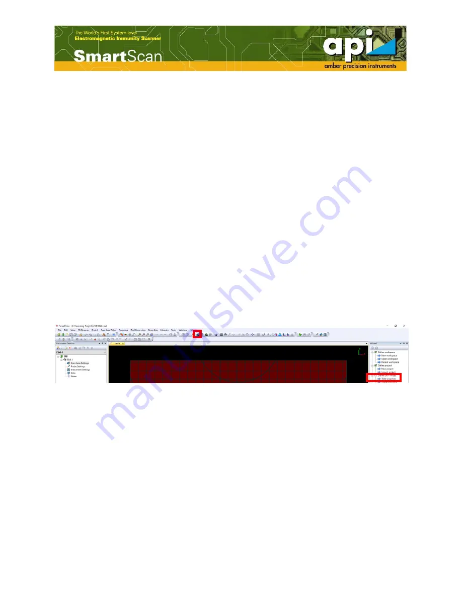
Click on "Snapshot" icon in the top menu bar, or double click on "Take snapshot" on
"Wizard" pane.
Figure 11: "Snapshot" icon and "Take snapshot" shortcut.
c.
Move the robot to proper XY position to capture the desired scan area using four direction
arrows with desired moving step, shown in Figure 12. It is always good to press the camera
icon to move the robot to the camera position first, and then start moving XY direction.
"Step" in "[deg]" is the rotation step in degree. The camera can be lowered to take the DUT
picture if the DUT is small. When the desired scan area is too large to capture by the camera,
the "Image stitching" option can be used to capture the large DUT image. Details about
"Image stitching" and "Import DUT image" are given at Appendix-A.


