D
OUTPUT
D.5
LIR Crossover Filtering
D.5
LIR Crossover Filtering
Unique to APG, Linea Impulse Response (LIR) crossover filtering gives a Linear Phase crossover
which has a constant delay regardless of frequency (unlike other types of crossover which delay
different frequencies to a different extent, thus smearing the arrival time). The LIR crossover
can thus be described as having a flat Group Delay response, and thus entirely free of Group
Delay Distortion, this is exactly the same as can be provided by common FIR filtering but
without the complications and disadvantages inherent with the FIR technique. The shape of
the LIR crossover filter is similar to a 4
th
order Linkwitz-Riley filter, and maintains zero phase
difference between the adjacent bands across the crossover region to keep the polar response
rock steady. Linear Phase filtering necessarily introduces delay; the laws of physics demand it.
To keep this delay to a minimum, it is recommended that more conventional crossover shapes
(such as Linkwitz-Riley) are used for the very lowest frequency high-pass edge, particularly if
this is less than perhaps 100Hz, which is well below the frequency thought to cause audible
Group Delay Distortion. This constant delay will depend on the lowest high-pass frequency
used in the crossover filters in a given Drive Module.
Also see Latency Delays on page 25.
D.6
Parametric Equalisation
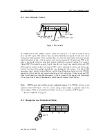
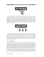
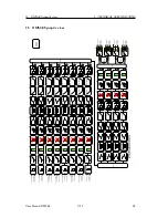
There are ten different EQ filters, two shelving filters and eight parametric filters. Parametric
filters are defined by frequency, bandwidth and gain. The frequency is controlled by encoder
A
and ranges from 10Hz to 25.6kHz. The bandwidth, shown as Width on the screen, is controlled
by encoder
B
and ranges from 0.10 octaves to 5.2 octaves. Bandwidth can be shown and
asjusted as Q or Octaves (Oct). Gain is controlled by encoder
C
and is available in 0.2dB
increments.
Also see Bandwidth Units on page 23.
D.7
Limiters
The DMS48 includes three limiters in the output signal path.
D.7.1
Vx Limiter
1
LIM
Out
n
ame
Thresh
20.0dB
Over
2.0dB
VxMode
Off
This is a peak-detecting signal limiter. The VX Mode parameter determines the style of
limiter. When Virtual Crossover (VX) mode is off, the limiter is controlled in a conventional
manner, the only controls being Threshold and Overshoot. The Overshoot limiter prevents the
signal from exceeding threshold during the attack phase of the main limiter by more than a
predetermined amount. The optimal Overshoot setting is usually about 8dB. Lower Overshoot
settings will sound progressively harder. When VX mode is engaged, the user can choose
the crossover point of a virtual crossover, which gives two limiters per output so the user
can individually limit the drivers in a passive 2-way enclosure using individual thresholds, and
optimised attack and release characteristics for each. The Threshold of the second Hi limiter,
is set relative to the threshold of the first Lo limiter. The effect of the VX threshold and split
frequency on the Limiter curve can be seen in PWAPG. This Limiter introduces some delay. In
User Manual DMS48
V1.1
21
Summary of Contents for DMS48
Page 1: ...User Manual Digital Processor DMS48...
Page 2: ......
Page 29: ......
Page 30: ......
Page 31: ......

