53
code HG0141.00GB ed.A-2008
LRP - RAPID PRO and LK - KONDENSA
LRP and LK WARM AIR HEATER
1 2 3 4 5 6 7 8
HG0131.00 A 005
HG0131.00 A
014
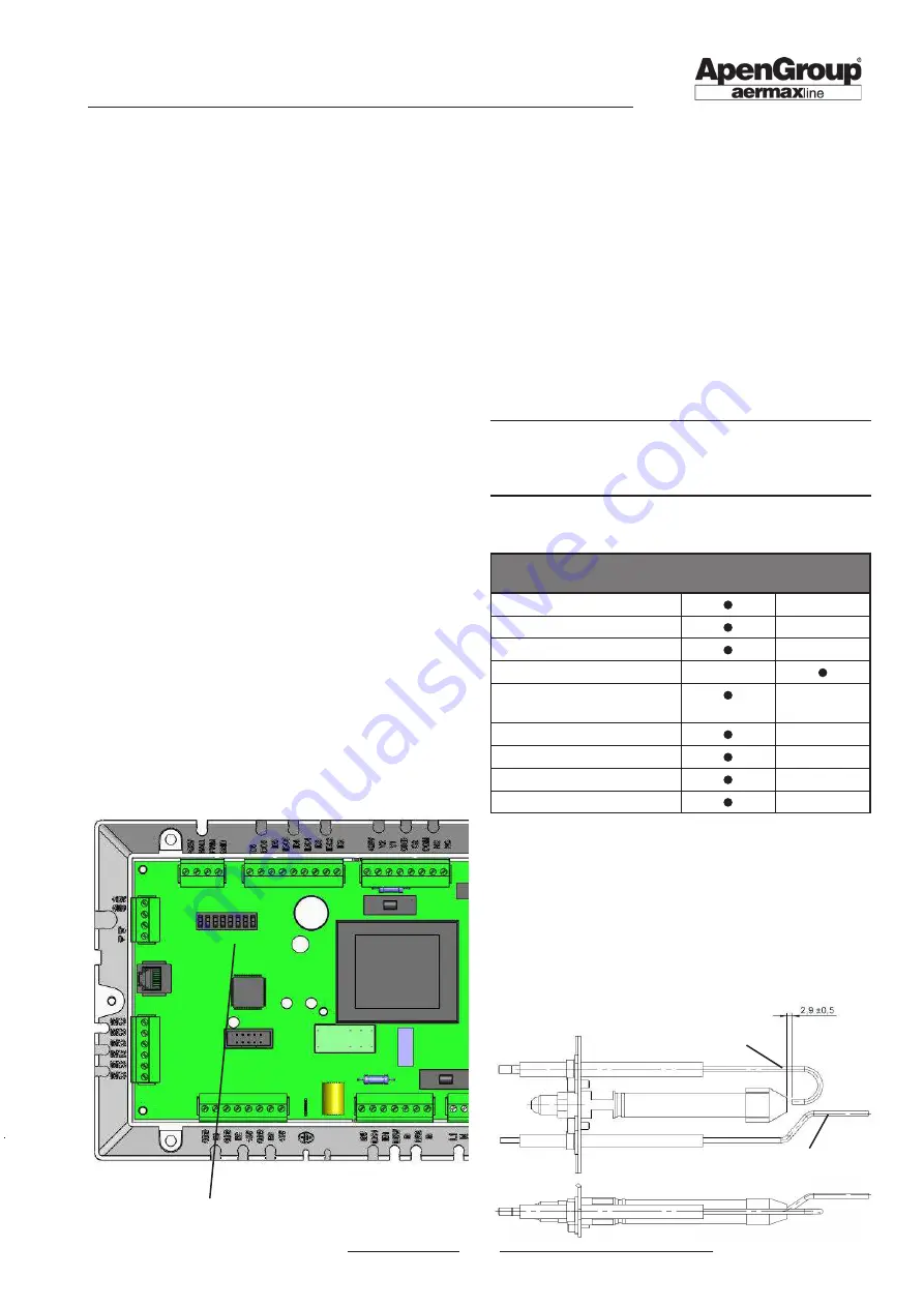
7.11. Replacing the modulation PCB
When replacing the PCB, it is required to carry out a few checks
and set a few parameters through the LCD command or Smart
Web/Easy.
Every LRP and LK heater has a list of pre-programmed default
values. It is advisable to update the list at every change performed
on site in order to be able to reprogram a spare PCB if needed.
Check the hardware configuration of the PCB
Modify the address of the PCB with the switches, copying the
exact configuration of the PCB that was just replaced.
Programming the parameters
The parameters that must be programmed are the following:
•
d0, d1, and d5 - to identify the type of equipment;
•
b1, b2, b3 - regulate the motor revolutions of the flue fan;
• S1 - enables the NTC1 hot air intake probe;
• ST1 is the set point value for NTC1;
• H51, H52 and H53 - to regulate the 0/10 Vdc (if provided);
• S2, ST2 and P2 - to heat the electrical compartment (if
provided).
• TH1 is the upper temperature limit above which you have
the F51 fault
Programming the parameters - Operating mode
Parameters can be modified from the LCD display on the ma
-
chine or, alternatively, from Smart Web/Easy.
The Smart Web/Easy can be used to access all parameters [see
tables on previous pages]; parameters have passwords, which
are issued by the APEN GROUP assistance service.
Please refer to the Smart Web/Easy manual for instructions for the
procedure for access and modification of functional parameters.
Please remember that all changes to parameters must be done
ONLY with the burner OFF (with display showing rdy or off).
8.
MAINTENANCE
To keep the heater efficient and guarantee a long lifetime of the
same, it is advisable to run some inspections at regular intervals:
1) check the status of start-up and detection electrodes, pilot
flame and relevant seal;
2) check the status of flue exhaust and air intake ducts and
terminals;
3) check the status of the Venturi pipe;
4) check and if necessary clean the exchanger and burner;
5) check and clean the water trap;
6) check the intake pressure at the gas valve;
7) check the operation of flame monitoring equipment;
8) check the safety thermostat(s);
9) check the ionization current.
NOTE: Operations at points 1, 2, 3, 4 and 5 must be per-
formed after disconnecting the heater from the electrical
mains and closed the gas supply. Operations at point 6,
7, 8 and 9 must be done with the heater on.
Maintenance interval chart
Maintenance
Every
year
Extraordinary
1) Electrodes and Pilot
2) Flue gas/Air Terminals
3) Venturi pipes
4) Exchanger/Burner
5) Trap and condensate
collection tray
6) Gas valve
7) Flame Equipment
8) Safety thermostat(s)
9) Ionization current
Verify that the start-up elec-
trode discharges on the
external edge of the pilot
burner.
Keep the detection electrode tangent to
the pilot burner.
Switch for Smart Web/Easy


