30
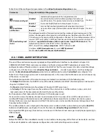
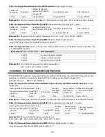
The error codes are the same as in the case of the MODBUS-RTU protocol (Table 18.5)
Example 19.4.
Error frame for a non-existing read register address:
0x00 - 0x00 - 0x00 - 0x00 - 0x00 - 0x05 - 0xFF - 0x84 - 0x02 - 0x0001
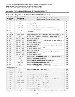
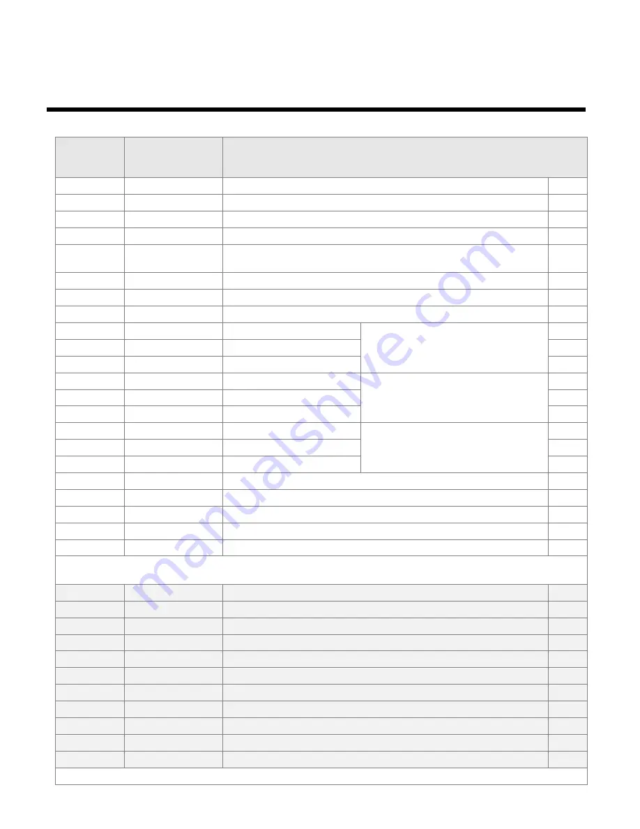
20. MAP OF DEVICE REGISTERS FOR THE MODBUS-RTU/TCP
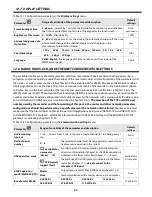
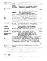
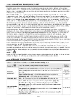
Table 20. Map of registers for the MODBUS-RTU and MODBUS-TCP protocols
Register
address HEX
(DEC)
Range of variability
or value of the
register (HEX or DEC)
Description of register and access type
(R- read only register, R/W - read and write register)
0x00 (0)
0
not used
R
0x01 (1)
407
device type identifier
R
0x02 (2)
100 ÷ 999
recorder's software (firmware) version
R
0x03 (3)
-300 ÷ 800
temperature of the AR18x wired probe, resolution 0.1
°C
, no comma
R
0x04 (4)
0 ÷ 15
current status of outputs 1, 2, 3, 4: bits 3, 2, 1, 0 bit=1 means the output
is switched on
R
0x05 ÷ 0x0B
0
not used or reserved
R
0x0C ÷ 0x1B
-9999 ÷ 19999
value of measurement channels 1÷16 (in the U2 code, 1 register/channel, 16-bit)
R
0x1C (28)
0 ÷ 6
day of the week in the internal RTC clock (counted based on the date)
R
0x1D (29)
0x0101 ÷ 0x630C
years (HB) and months (LB)
Internal real time clock (
RTC
, chapter 12.10)
R/W
0x1E(30)
0x0100 ÷ 0x1F17
days (HB) and hours (LB)
R/W
0x1F (31)
0x0000 ÷ 0x3B3B
minutes (HB) and seconds (LB)
R/W
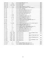
0x20 (32)
0x0101 ÷ 0x630C
years (HB) and months (LB)
Parameter
Start of the time limit
(chapter
12.2)
R/W
0x21 (33)
0x0100 ÷ 0x1F17
days (HB) and hours (LB)
R/W
0x22 (34)
0x0000 ÷ 0x3B3B
minutes (HB) and seconds (LB)
R/W
0x23 (35)
0x0101 ÷ 0x630C
years (HB) and months (LB)
Parameter
End of the time limit
(chapter
12.2)
R/W
0x24 (36)
0x0100 ÷ 0x1F17
days (HB) and hours (LB)
R/W
0x25 (37)
0x0000 ÷ 0x3B3B
minutes (HB) and seconds (LB)
R/W
0x26 (38)
1 ÷ 28800
Parameter
Data recording interval
(chapter 12.2) – number of seconds [s]
R/W
0x27 (39)
0 ÷ 5
Parameter
Recording type
(chapter 12.2)
R/W
0x28 (40)
0 ÷ 15
Parameter
Selection of permission channel
(chapter 12.2)
R/W
0x29 (41)
-9999÷19999
Parameter
Permission threshold value
(chapter 12.2)
R/W
0x2A (42)
0 ÷ 1
Parameter
Archive storage memory
(chapter 12.3)
R/W
Configuration parameters for the measurement channel number
KP
= 0÷15, 0=channel 1, 15=channel 16; a description can be
found in chapter 12.4
0x2B + KP*11
0 ÷ 3
Parameter
Assigned sensor type
(chapter 12.4)
R/W
0x2C + KP*11
0 ÷ 1
reserved
R
0x2D + KP*11
0 ÷ 9999
reserved
R
0x2E + KP*11
0 ÷ 16
Parameter
Address of assigned sensor (ID)
R/W
0x2F + KP*11
0 ÷ 9999
Parameter
Register address to read for RS485
R/W
0x30 + KP*11
0 ÷ 3
Parameter
Decimal dot position for the readout from the RS485 sensor
R/W
0x31 + KP*11
-9999 ÷ 19999
Parameter
Bottom of indication range for graphics
R/W
0x32 + KP*11
-9999 ÷ 19999
Parameter
Top of indication range for graphics
R/W
0x33 + KP*11
0 ÷ 8
Parameter
Assignment of alarm outputs
R/W
0x34 + KP*11
0 ÷ 8
Parameter
Assignment of measurement group
R/W
0x35 + KP*11
0 ÷ 22
Parameter
Background color
R/W
Configuration parameters of an alarm channel numbered
KA
= 0 ÷ 3 (0=channel 1, 3=channel 4), description in chapter 12.6
Summary of Contents for AR407
Page 32: ...32 21 USER S NOTES...


