


17
Notes: (1)
- in the case of a 90 MB file, the copying time is equal to approx. 11 min. (approx. 135 kB/s, also depending on
the type of memory)
(2)
-
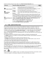
Archive storage memory
=
Internal
only
prevents unintentional creation of an archive in the USB
memory installed in the port by accident, in order to perform file operations, or by unauthorized personnel
(3)
– formatting deletes all data from the memory (with the exception of configuration files); this operation is
recommended in the event of problems with accessing data
NOTE:
!
- during file operations or formatting of memory,
do not shut down the power supply
and
do not take out the
USB memory,
as this may cause a loss of recorded data or the current configuration (parameters and names)
- until the file operations or memory formatting is completed, recording is stopped and transmission of files with
measurement data over the Ethernet from the ARSOFT-LOG level is blocked
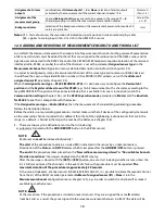
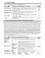
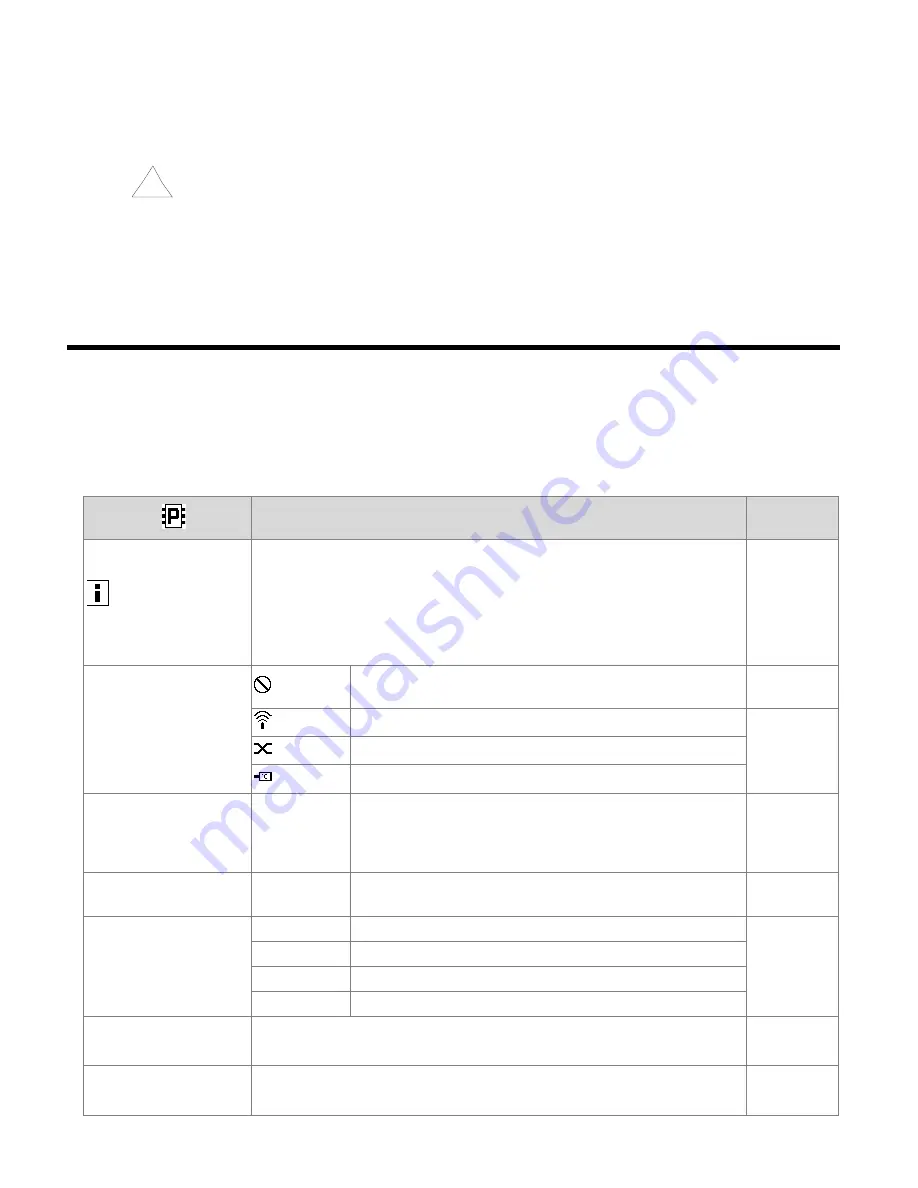
12.4. CONFIGURATION OF MEASUREMENT CHANNELS
The recorder can present and record data from a maximum of 16 measurement channels from wireless sensors of
the AR43x, series, from one wired temperature probe (AR182 and AR183), and through the RS485 interface from
any Apar devices using the MODBUS-RTU protocol.
As a default, the device is delivered with an empty list of measurement channels. In order to present the data, new
sensors/devices (radio and wired, chapter 12.5) must be added to the list.
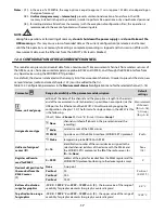
Table 12.4. Configuration parameters in the
Measurement channel
configuration menu for the selected channel (1
÷
16)
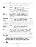
Parameter
Range of variability of the parameter and description
Default
settings
Name, unit and group
edition of the name of the channel and the group (max. length 16 characters)
and of the measurement unit (4 characters) is possible on a computer (via the
USB port or the Ethernet and the ARSOFT-CFG software or by copying the
configuration - chapter 12.3). The format of a single section in the
AR407.txt
file
is the following:
[Chan1] Name=
Channel 1
, Unit=
°C
, [
Group1]
Name
=
Group 1
Measurement
of channel i
(for i=1÷16),
°C, Group j
(
for j=1÷8
)
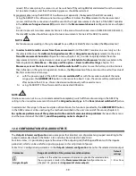
Assigned sensor type
None
channel switched off (absent in the presentation and the
recording)
Radio
wireless sensor of the AR43x series
Radio
RS485
Apar device with the RS485 interface (MODBUS-RTU protocol)
Probe
temperature probe
AR182 or AR183
Address of assigned
sensor (ID)
0 ÷ 16
identification number of the sensor/device assigned to the
selected channel (address of the device with the RS485 and
the MODBUS-RTU protocol or the
ID
of the radio sensor, for
ID
=16=
None
)
None
(16)
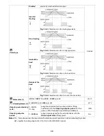
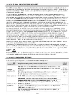
Register address to
read for RS485
0 ÷ 9999
address of the register for readout from the RS485 register and the
MODBUS-RTU protocol (conforming to the device registers map)
0
Decimal dot position for
the readout from the
RS485 sensor
(1)
None
0, no point
Position 1
(0.0/0.1
°C
)
Position 1
0.0
Position 2
0.00
Position 3
0.000
Bottom of indication
range for graphics
-199.9
÷
1999.9°C
or
-9999
÷
19999
units
(2)
– the lower value of the range of
variability for graphic elements (bar graph, counter, diagram)
0.0 °C
Top of indication range
for graphics
-199.9
÷
1999.9°C
or
-9999
÷
19999
units
(2)
– the upper value of the range of
variability for graphic elements (bar graph, counter, diagram)
100.0 °C
Summary of Contents for AR407
Page 32: ...32 21 USER S NOTES...