background image

EN 


48 


Accident prevention 

Before starting up the machine: 
Read this manual carefully. Ensure no children, animals or unauthorised persons are in the vicinity of the 
machine. Carefully check that the machine and external safety devices function correctly.  
 
During machine operation: 
Never leave the machine unattended. Pay attention to abnormal noises or machine behaviour. Keep away 
from  moving  members.  Never  open  the  mobile  protective  cover  before  the  spiral  tool  has  completely 
stopped rotating. 
 
Upon completion of a work cycle: 
Empty the contents of the machine bowl completely. Turn off the main switch and disconnect the 
machine from the electrical supply ensuring that the electrical panel on the machine and the machine 
power cable are isolated from the main power supply in a safe manner for the entire duration of the 
intervention, without accidental risk of re-energising of the power supply. Clean the machine, as per the 
procedures specified in this manual.  


Machine tests carried out by the manufacturer 

The manufacturer, before placing a machine on the market, carries out a series of tests to ensure that the 
machine functions correctly: 


Functional tests to check the electrical system and grounding. 


Functional tests to check the mixer functions. 


Tests to check the AERIAL NOISE level: less than 70 dB (A). 

Summary of Contents for BAKERY line V Series

Page 1: ...INSTRUCTION AND MAINTENANCE MANUAL 2 40 English 41 96 SPIRAL DOUGH KNEADING MACHINE WITH FIXED BOWL MODEL V V R Serial number Year of construction 2020...

Page 2: ...RU V V R 2020 2 400 50 3 5 35 11 05 12 26 24 2 EAC...

Page 3: ...RU 3 1 5 2 7 CE 7 3 8 8 8 9 9 4 10 5 11 11 11 11 11 6 12 12 12 12 7 13 8 14 14 14 15 9 16 16 16 17 10 17 17 11 18 18 18 18 12 19 19 19 20 20 20 20 13 21 21 21 23 23 14 25 15 26...

Page 4: ...RU 4 1 2 3 4 5 i ii...

Page 5: ...RU 5 1...

Page 6: ...RU 6...

Page 7: ...RU 7 2 CE CE 2 2...

Page 8: ...RU 8 3...

Page 9: ...RU 9 70 A...

Page 10: ...RU 10 4...

Page 11: ...RU 11 5 55 2 1 2 Start Stop Start 1...

Page 12: ...RU 12 6 20 C 40 C 90...

Page 13: ...RU 13 7 A B C C A 2...

Page 14: ...RU 14 8 25x130 3 5...

Page 15: ...RU 15 D A B C B C A D...

Page 16: ...RU 16 9 5 40 C 90 500 500 500...

Page 17: ...RU 17 C B B C 10 D D...

Page 18: ...RU 18 11 B C A D 3 A B D C B...

Page 19: ...RU 19 12 A 2 1 2 3 start A...

Page 20: ...RU 20 A 1 Start A Start BOWL JOG button Start O BOWL JOG button...

Page 21: ...RU 21 13 0...

Page 22: ...RU 22...

Page 23: ...RU 23 o o o M6 M8 M10 M12 M14 M16 8 8 Nm 9 7 23 47 80 130 196 10 9 Nm 13 6 33 6 113 180 275 Nm 6 16 32 56 135...

Page 24: ...RU 24 3...

Page 25: ...RU 25 14 I 1 2 3 4 5 1 2 3 4 5 Start 1 2 1 2 1 1 1 2 1 2 1 2 1 2...

Page 26: ...RU 26 15 PET ABS PST o o...

Page 27: ...RU 27 1 SITEC 72X144 0 10 0 20 72x144...

Page 28: ...RU 28 Reverse 1 BOWL JOG...

Page 29: ...RU 29 backup backup 2a...

Page 30: ...RU 30 0 10 0 20 C 0 M 0 E 0 1...

Page 31: ...RU 31...

Page 32: ...RU 32 1...

Page 33: ...RU 33 1...

Page 34: ...RU 34 Reverse 1 1 5 JOG BOWL JOG BOWL...

Page 35: ...0 125 150 117 131 189 266 306 378 670 670 750 850 910 1000 851 881 930 946 946 946 1122 1122 1248 1499 1560 1650 694 694 775 879 940 1035 1406 1406 1522 1612 1612 1612 340 350 505 695 705 755 2 3 7 2...

Page 36: ...38x88x160 h 485 80 128x81x150 h 380 138x88x160 h 420 138x88x160 h 490 120 138x88x168 h 555 140x90x177 h 595 140x90x177 h 665 160 162x107x176 h 765 165x110x187 h 785 165x110x187 h 835 200 162x107x176 h...

Page 37: ...RU 37 3 H B F A B F...

Page 38: ...RU 38 1 2 3 F 4 B H 5 6 B H 4 A 7 B H F 8 9...

Page 39: ...RU 39 A D E C B...

Page 40: ...RU 40 A B 1 4 2 B 3 4 B C B A A B A 1 D 2 E A 3 4 C B 1 B C D A...

Page 41: ...0 400 Volt 50 Hz 3 PH 2 speeds with double scale electro mechanical timer Sitec 72x144 with stainless steel grid Serial number Year of construction 2020 Number of speeds 2 Voltage V 400 Frequency Hz 5...

Page 42: ...N OF THE MACHINE AND POSITION OF THE OPERATOR 55 Operating conditions 55 Position of the machine and of the operator 55 Fixing the machine in place 56 10 ELECTRICAL SYSTEM 57 Connection to the power s...

Page 43: ...cal characteristics and packaging Appendix 3 Adjustment of the tension of the transmission belts Appendix 4 Wiring diagrams Appendix 5 Exploded views N B i The technical data is not binding The data c...

Page 44: ...ealth that has been suitably trained to operate the machine i e that has a good knowledge of the machine functions the machine regulations the safety devices and protections installed on the machine t...

Page 45: ...ce of live parts Before carrying out any type of intervention on the machine interrupt the power supply to the machine by turning off the main switch and ensuring that the electrical panel on the mach...

Page 46: ...ine the serial number the year of construction the voltage frequency and number of phases the total power absorbed kW The electrical characteristics voltage frequency number of phases and power absorb...

Page 47: ...ry to observe the safety warnings and signs on the machine itself in the work environment and on the products used which point out for example electrical mechanical or thermal risks the risk of slippi...

Page 48: ...chine bowl completely Turn off the main switch and disconnect the machine from the electrical supply ensuring that the electrical panel on the machine and the machine power cable are isolated from the...

Page 49: ...panel on the machine and the machine power cable are isolated from the main power supply in a safe manner for the entire duration of the intervention without accidental risk of re energising of the p...

Page 50: ...of its shape and movement mixes and refines the ingredients by pushing them against the breaking column and the sides of the bowl The bowl as a result of its rotation constantly brings dough still to...

Page 51: ...be between 20 and 40 C while the humidity of the environment must not exceed 90 Storage of the unpacked machine When the machine has already been unpacked in addition to the above specified conditions...

Page 52: ...hick cardboard box machine placed in a wooden crate machine placed in a wooden box The information concerning the gross weight appears on the outside of the packaging In order to unpack the machine it...

Page 53: ...from the pallet While moving the machine keep it close to the ground Ensure that the area across which the load is moved is clear of objects persons and animals Wear suitable protective clothing Lifti...

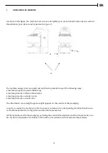
Page 54: ...the machine in this manner pay attention to the following precautions The machine must be moved slowly and carefully The machine must only be moved across flat smooth solid surfaces without changes in...

Page 55: ...electromagnetic environment Cleanliness of the work environment The machine may only be used in environments suitable for the storage and production of food products Furthermore it is necessary to res...

Page 56: ...ect to the machine Fixing the machine in place Machine stability The machine must rest on a horizontal smooth solid surface without level changes Once the machine has been correctly positioned in the...

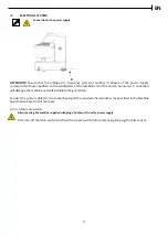
Page 57: ...otor an incorrect connection will damage the machine and will invalidate the guarantee Connect the power cable D to a socket having all the required characteristics as specified in the Machine Specifi...

Page 58: ...damage the internal surface of the bowl and the mixing tools Use water and if necessary a food grade soap to clean the bowl Rinse the bowl thoroughly Sanitise the bowl as specified by local sanitation...

Page 59: ...ndix 2 The recommended sequence for loading the ingredients is as follows 1 Pour the required quantity of water into the bowl 2 Pour the flour into the bowl in the correct proportion with respect to t...

Page 60: ...ine to permit it to be easily extracted by the operator Warnings relative to repeated interruptions of a work cycle Once the work cycle has been started by pressing the Start button the machine contin...

Page 61: ...itable for the task to be carried out clothing which must offer protection against organic chemical biological mechanical and or electrical risks switch off the machine and disconnect it from the powe...

Page 62: ...head Stop Emergency push button the power supply to all the electrical machine components is interrupted and therefore all the machine functions are disactivated The machine function being executed s...

Page 63: ...ts must be replaced when they start to fray or when under excessive tension before they actually break It is necessary to replace the entire set of belts relative to a transmission even if only one of...

Page 64: ...for the task to be carried out switch off the machine and disconnect it from the power supply before carrying out any operation on the machine The procedure for the adjustment of the belt tension and...

Page 65: ...lace the light bulb 5 Release the Emergency button by rotating it clockwise When the Start button is pressed the machine does not start 1 The mobile bowl cover is open 2 There is a fault in the safety...

Page 66: ...and drawing of steel profiles welding machining Disassembly and disposal of the machine The buyer is directly responsible for putting the machine out of service The disassembly of mechanical and elect...

Page 67: ...quired For additional information on the machine operation contact the manufacturer All the controls required to operate this machine model are located on the control panel as shown in the figure belo...

Page 68: ...place the machine under excessive stress MANUAL BOWL JOG BUTTON Impulsively rotates the bowl without rotating the spiral even when the mobile bowl cover is open The direction of rotation of the bowl...

Page 69: ...des when the mobile bowl cover is closed Manual mode Semi automatic mode Automatic mode These operating modes are selected using the special timer composed of a first speed dial located to the left wh...

Page 70: ...t 1 second with the selector in the central position in order to stop the rotation Press the EMERGENCY STOP button to end the manual cycle in first speed To work in manual mode in second speed Set the...

Page 71: ...g the bowl rotation direction wait 1 second with the selector in the central position in order to stop the rotation The mixer stops automatically when the time set on the first speed dial has elapsed...

Page 72: ...speed this function is automatically disabled when the machine is running in second speed N B The reverse clockwise bowl rotation function can only be used for a maximum time of 1 minute the reason b...

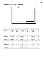
Page 73: ...7 131 189 266 306 378 Bowl diameter mm 670 670 750 850 910 1000 Floor to bowl rim height mm 851 881 930 946 946 946 Length mm 1122 1122 1248 1499 1560 1650 Width mm 694 694 775 879 940 1035 Height mm...

Page 74: ...Weight kg AxBxH cm Weight kg 60 128x81x150 h 375 132x85x166 h 415 132x85x166 h 485 80 128x81x150 h 380 132x85x166 h 420 132x85x166 h 490 120 138x88x168 h 555 137x87x176 h 595 137x87x176 h 665 160 162...

Page 75: ...re carrying out any operation on the machine it is obligatory to wear protective clothing suitable for the task to be carried out switch off the machine by turning off the main switch and disconnect t...

Page 76: ...the nuts B and H in the position described in point 4 tighten both the nuts in pos A so as to move the motor away from the spiral tool belt pulley parallel to the head until the required tension has...

Page 77: ...ectrical panel on the machine and the machine power cable are isolated from the main power supply in a safe manner for the entire duration of the intervention without accidental risk of re energising...

Page 78: ...s B as described in the above procedure PROC A 1 Loosen the upper nut in position D 2 Lift the transmission support E enough to be able to remove the belts A 3 Replace the belts with the new ones whic...

Page 79: ...EN 79 APPENDIX 4 WIRING DIAGRAMS V 60 80 120 2V MODEL with electro mechanical timer SITEC 72x144 POWER WIRING DIAGRAM...

Page 80: ...EN 80 APPENDIX 4 WIRING DIAGRAMS V 60 80 120 2V MODEL withelectro mechanical timer SITEC 72x144 CONTROL WIRING DIAGRAM...

Page 81: ...LEGRAND 10 A GL 1 Fuse holder WEBER 3 SQ 1 Limit switch SCHNEIDER XCKN 2103 P 20 1 J1 24 pole F connector MOLEX 1 CONTROL PANEL KT 1 Timer SITEC 72 X 144 1 SB1 Emergency Stop push button EATON M 22 P...

Page 82: ...EN 82 APPENDICE 5 ESPLOSO V 60 80 all V 50hz APPENDIX 5 EXPLODED VIEWS OF V 60 80 all V 50hz MIXER AND PARTS LIST ESPLOSO STRUTTURA MACCHINA EXPLODED VIEW OF MACHINE STRUCTURE...

Page 83: ...643002 8 Chiusura posteriore superiore Upper rear plate 1 700004 9 Piedino in plastica M16x110 Foot M16x110 2 P01001 10 RuoteNylon 120 f 12 sp 35 Nylon wheel 2 698002 11 Ruota girevole 100 H 128 Revol...

Page 84: ...EN 84 ASSIEME GRUPPO SPIRALE EXPLODED VIEW OF SPIRAL TOOL ASSEMBLY...

Page 85: ...4 Coppetta protezione spirale Spiral tool protection cup 1 635001 5 Distanziale cuscinetti spirale Spiral bearings spacer 1 643001 6 Ghiera M35x1 57 Nut M35x1 57 1 607002 7 Spirale Spiral tool 1 7200...

Page 86: ...30001 2 MotoreperVis60kw3 7 2 06400v50hz Spiralmotor for VIS 60 kw 3 7 2 06 400v 50 hz Motore per VIS 80 kW 2 6 4 8 50 Hz 400 V Spiral motor for VIS 80 kW 2 6 4 8 50 Hz 400 V 1 1 M53001 M53002 3 Blocc...

Page 87: ...EN 87 ESPLOSO GRUPPO VASCA EXPLODED VIEW OF THE BOWL ASSEMBLY...

Page 88: ...ione vasca Bowl protectiondisk 1 642001 5 Albero vasca Bowl shaft 1 600009 6 Ghiera M50x1 5 Nut M50x1 5 1 607001 7 Anello Nylos 32210 AV Nylos ring 32210 1 A04001 8 Vasca VIS 60 Bowl VIS 60 Vasca VIS...

Page 89: ...izione Description Qt Qty Codice Code 1 Slitta motore vasca Bowl motor plate 1 730002 2 Perno slitta motore vasca Bowl motor plate pin 1 686001 3 Puleggia SPZ 2 gole Pulley SPZ Z 2 1 680004 4 Motore 0...

Page 90: ...EN 90 ESPLOSO GRUPPO RINVIO VASCA EXPLODED VIEW OF BOWL TRANSMISSION ASSEMBLY...

Page 91: ...nello Seeger E40 UNI 7435 Seeger ring E40 Uni 7435 1 B23001 5 Puleggia SPZ 5 gole p 60 e 64 f 35 Pulley SPZ e 64 f 35 Z 5 1 680011 6 Linguetta 10x8 L 50 UNI 6604 Key 10x8 L 50 UNI 6604 1 B24005 7 Cale...

Page 92: ...ion Qt Qty Codice Code 1 Supporto rullo reggispinta Thrust roller support 1 714005 2 Rullo reggispinta Thrust roller 1 698001 3 Cuscinettoradialeasfere6202 2RS Ball bearing 6202 2RS 2 K10006 4 Perno r...

Page 93: ...bowlcover for VIS 120 Riparo mobile trasparente per VIS 120 Transparent mobile bowl cover for VIS 120 1 1 702007 702013 2 Supporto SX riparo Left support for mobile bowl cover 1 714018 3 Supporto DX r...

Page 94: ...Timer 72x144 Electro mechanical timer SITEC 72x144 1 E50005 3 Spia luminosa Power ON light 1 E61001 4 Selettore bypass Bypass selector 1 E59001 5 Pulsante START START push button 1 E60001 6 Selettore...

Page 95: ...Description Qt Qty Codice Code 1 Bussola filettata per testa Threaded bush 1 616004 2 Boccola DU 16 18x25 Bush DU 16 18x25 1 K13001 3 Ghiera autoblocc GUK M25x1 5 Self locking nut GUKM25x1 5 1 B28004...

Page 96: ...sition Descrizione Description Qt Qty Codice Code 1 Bussola filettata per testa Threaded bush 1 616004 2 Boccola DU 16 18x25 Bush DU 16 18x25 1 K13001 3 Ghiera autoblocc GUK M25x1 5 Self locking nut G...

Page 97: ...97 Equip Group 125080 2 7 495 234 00 33 http equipgroup ru http bakery apach it...

Reviews: