background image

21

9

Programming Software Installing and Starting (in windows XP system)

Install USB Cable Driver Programme

Double click ”AT-778V-Setup.exe/AT-778U-Setup.exe“, then follow the installing instruction.

Click  start  menu  in  computer,  under  “ALL  PROGRAMS”  menu,    

1. 

choose and click “USB To Com port” in AT-778V/U program, install  
“USB To Com port” driver by indication.
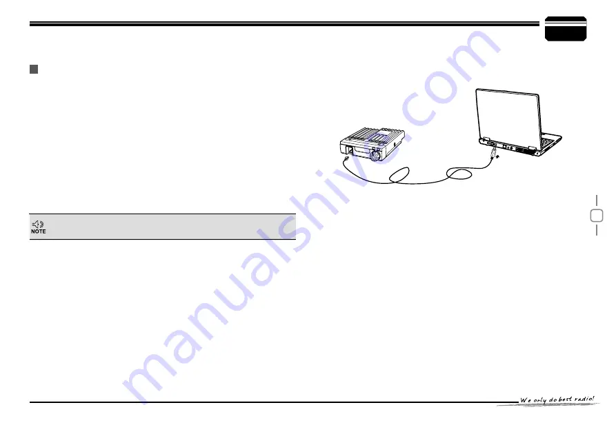
Connect the optional PC55 USB Programming cable to USB port in   

2. 

PC with transceiver.
Double click AT-778V/U shortcut or click AT-778V/U inprocedure index 

3. 

of start menu, choose serial com port as indicated then click OK to 
start programming software.
According to instruction,select correct"COM Port,  then click "OK" to 

4. 

start programming software.

Even in same computer,the selective COM Port is different  when 
USB cable connects with  different USB port.

You shall install software before connecting the USB cable line. Switch 
on transceiver before writing frequency.You had better not switch on or 
off the power supply of transceiver when it is connected with computer, 
otherwise, it will make transceiver unable to read or write frequency. In 
this case, you have to turn off programming software, pull out USB cable. 
then reinsert USB cable and open software, then rechoose COM Port, 
it will turn into normal operation. Therefore, please connect transceiver 
with computer after switching on the transceiver. Don't restart transceiver 
power when it is connected with computer.

OFF

NO

Summary of Contents for AT 778

Page 1: ...A1 160105 ...

Page 2: ......

Page 3: ......

Page 4: ...and it pursues company philosophy of innovation and practicality NOTE When programming the transceiver read the factory initial data firstly then rewrite the frequency and signaling etc otherwise errors may occur because of different frequency band etc Models Apply To This Manual AT 778V AT 778U Mobile radio AT 778 Mobile Radio Applicable Software AT 778 ...

Page 5: ...n the coming years Do not attempt to configure your transceiver while driving it is dangerous This transceiver is designed for a 13 8V DC power supply Don t use a 24V battery to power on the transceiver Do not place the transceiver in excessively dusty humid or wet areas nor unstable surfaces Please keep it away from interferential devices such as TV generator etc Do not expose the transceiver to ...

Page 6: ...nnel mode 11 Adjusting Frequency Channel 11 Receiving 11 Transmitting 11 Transmitting Tone Pulse 12 Roger beep 12 ransmitting audio signal 12 Channel Edit 12 Channel Delete 12 Shortcut Operations 13 squelch off squelch off momeNTARY 13 Squelch level Setup 13 Frequency Channel Scan 13 Scan Skip 13 CTCSS DCS Encode and Decode setup 13 Channel Scan 14 DCS SCAN 14 FM radio 14 Power level control 14 Of...

Page 7: ...ast ratio setup 19 Backlight color 19 backlight brightness 20 voice prompt setup 20 Automatic Power on 20 Reset Factory Default 20 Programming Software Installing and Starting in windows XP system 21 Install USB Cable Driver Programme 21 Maintenance 22 Default Setting after Resetting 22 Trouble Shooting 22 Specifications 23 Attached Chart 24 50 groups CTCSS Tone Frequency Hz 24 1024 groups DCS Cod...

Page 8: ...te buttons reasonably convenient for operation Adopt superior quality material better technology and high quality radiator to ensure stable and durable operation 512 programmable memory channels identiied by editing name Sperate CTCSS DCS setting for each single channel rejecting extra calling from other radios Various scan functions including CTCSS DCS Scan function Seperate band width setting fo...

Page 9: ...ox and packaging Transceiver Hardware Kit for Bracket Microphone Hanger Tapping screws S Washer for radio Adjust knob S Washer for hanger Tapping screws Microphone PC cable PC55 Car Antenna QCA 01 Programming Software AT 778V U Regulated Power Supply QRP 01 External Speaker SP 01 User Manual Microphone Mobile Bracket Spare Fuses 10A 250V QF 02 Fixing pad DC Power Cable with Fuse Holder QPL 01 OFF ...

Page 10: ...y 1 Route the DC power cable supplied with the transceiver directly to the vehicle s battery terminals using the shortest path from the transceiver We recommend you do not use the cigarette lighter socket as some cigarette lighter sockets introduce an unacceptable voltage drop The entire length of the cable must be dressed so it is isolated from heat moisture and the engine secondary high voltage ...

Page 11: ...e The recommended current capacity of your power supply is 12A 1 Connect the DC power cable to the regulated DC power supply and ensure that the polarities are correct Red positive Black negative 2 Connect the transceiver s DC power connector to the connector on the DC power cable Press the connectors firmly together until the locking tab clicks Fixed Station Operation REPLACING FUSES If the fuse ...

Page 12: ...ceiver via feed lines having an impedance other than 50Ω reduces the efficiency of the antenna system and can cause interference to nearby broadcast television receivers radio receivers and other electronic equipment Antenna Connection Transmitting without first connecting an antenna or other matched load may damage the transceiver Always connect the antenna to the transceiver before transmitting ...

Page 13: ... pads to fix the microhone hanger To utilize the optional AT 778 software you must first connect the transceiver to your PC then using an optional programming cable PC55 via Data socket Please use AT 778V U software for programming Ask your dealer about purchasing a Programming Cable PC55 For voice communications connect a microphone equipped with an 8 pin modular plug into the modular socket on t...

Page 14: ... MHz MHz step size Key 7 SC SKP Ssan delete add key 8 V M VFO Memory mode switch key 9 VOL Volume reduce key 10 VOL Volume increase key 11 DCT CTCSS DCS setting key 12 PTT Transmit key 13 SQL Squelch key 14 RX indicator Light on when squelch valid 15 TX indicator Light on during transmitting 16 MIC Speak into it during transmitting 17 LCD display Display channel frequency function setting 18 Speak...

Page 15: ...M FUNCTION 1 Antenna connector Connect a 50 ohm antenna 2 Ex Speaker Jack Connect optional SP 01 external speaker 3 Power cable Connect optional SP 01 external speaker Connect a standard DC power cable NO KEY FUNCTION 1 MHz Wide Narrow band switch 2 V M Delete memory channel NO KEY FUNCTION 1 FUN SET Enter setting mode after hold it for 2 seconds 2 SQL Turn on Monitor 13V GND RXD TXD MIC GND MIC S...

Page 16: ...setting VOL SQ level 6 Displays during receiving or when Monitor is ON 7 Displays signal strength 8 Displays when setting band width 9 Displays when sending RB TB CL 10 Displays H M L power level setting 11 Displays when Automatic power off function on 12 Displays when setting CTCSS DCS 13 Display when setting offset direction 14 Displays when key lock function on 15 Displays current voltage level...

Page 17: ...ial settings As pic 1 Amateur Transceiver Mode 222 Except setting as CH mode others considered as Amateur transceiver mode Under this mode press V M key to switch between Channel mode and VFO mode Channel Name Tag Mode BBB When set display as NM it enters into Channel Name Tag mode At this mode it will display corresponding channel name when the current channel is edited with name Otherwise it wil...

Page 18: ...me Short press FUN SET and or to increase VOL or VOL decrease volume by 10 steps During receiving press 222 to temporary mute the speaker the LCD displays VOL MT press any key to exit mute mode In frequency mode Short press 111 or to increase or decrease frequency by one step size Hold or to DN POW UP DN POW UP fast increase or decrease frequency Short press MHz the MHz will flash hold or will cha...

Page 19: ...VFO mode press 111 or MHz to choose wanted frequency Press 222 DCT key to enter CTCSS DCS setup Press to select the signaling Enter channel menu No 1 10 and choose 333 related setup Press 444 FUN SET key the LCD displays F if the M icon not flash means current channel number is valid If M icon flashes means current channel number is empty Press 555 key choose wanted channel number Press 666 V M ke...

Page 20: ...ft side of the LCD displays 111 S the current channel added to scan list this channel will be scanned when scan function start When the 222 S disappears the current channel is deleted from scan list this channel will not be scanned when start scan function When the LCD displays TSQ means 111 current channel set with CTCSS code press or to choose wanted code When the LCD displays DCS means 222 curr...

Page 21: ...SS scan mode Once finding a mathcing CTCSS signaling it will stop for 15S then scan again Press any key exit Repeatedly press DCT until LCD displays TSQ Press SC SKP to enter CTCSS scan mode Once finding a mathcing CTCSS signaling it will stop for 15S then scan again Press any key exit Press to switch between FM radio and two way radio mode In FM radio mode Press 111 V M to switch between frequenc...

Page 22: ...en press MHz the LCD displays the offset direction and offset frequency Repeatedly press 222 MHz key to choose positive or negative offset When the LCD display 333 Icon it indicates positive offset the transmitting frequency is higher than receiving frequency When the LCD display 444 Icon it indicates negative offset the receiving frequency is higher than transmitting frequency Press or to change ...

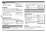
Page 23: ...e a mathcing carrrier CTC You can hear the calling when receive a mathcing carrrier and CTCSS DCS signaling Defualt SQ Enter No 02 function menu the LCD displays POW HI This function use to control transmit power level Enter No 03 function menu the LCD displays BNAD 25 Select suitable bandwidth in accordance with different local conditions 25 band width is 25k Wide band 20 band width is 20k Middle...

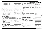
Page 24: ...lt OFF Enter No 06 function menu the LCD displays CAL OFF Hold PTT then press UP to transmit pre programmed audio signaling to check if the receiver is near the radio and not necessary to speak into microphone to confirm 1 8 group audio sound available OFF Turn off RB function Default OFF Enter No 07 function menu the LCD displays Press 111 or key to choose characater for present cursor ocation Pr...

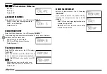
Page 25: ...el mode Default FR Enter No 14 function menu the LCD displays APO OFF Once APO is activated the radio will be automatically switched off when the pre set timer is running to end Enter No 11 function menu the LCD displays STP 12 5 This function valid only in frequency VFO mode input frequency or frequency scanning all restricted by frequency step size Total 9 Channel step size available 2 5K 5K 6 2...

Page 26: ...Default level 1 Enter No 17 function menu the LCD displays SCAN TO Enter No 18 function menu the LCD displays MIG 7 1 16 Total 16 levels available Default level 7 EEnter No 19 function menu the LCD displays BRI 10 1 30 Total 4 level backlight available Default level 10 EEnter No 20 function menu the LCD displays COL OR This radio has 3 backlight colors OR Orange Pilot Frequency TOT TIME OUT TIMER ...

Page 27: ... available OF Turn off Voice prompt function Default groups 5 Enter No 23 function menu the LCD displays AOP ON When this function is off the radio will not power on when connect power supply by turn power On Off knob user need press MIC key ON Automatic power on fucntion is on OFF Automatic power on fucntion is off Default ON Enter No 24 function menu the LCD displays RESTORE If your radio seems ...

Page 28: ...ng to instruction select correct COM Port then click OK to 444 start programming software Even in same computer the selective COM Port is different when USB cable connects with different USB port You shall install software before connecting the USB cable line Switch on transceiver before writing frequency You had better not switch on or off the power supply of transceiver when it is connected with...

Page 29: ...TCSS or DCS squelch off e Key and Dial do not function Key lock function is activated Cancel Key lock function i Rotating Dial will not change memory channel Transceiver is in CALL mode Press the VFO or memory mode g PTT key is pressed but transmission does not occur Microphone connection is poor Connect microphone properly Antenna connection is poor Connect antenna properly Default Setting after ...

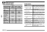
Page 30: ... 51Kg Receiver ETSI EN 300 086 standard testing Wide band Narrow band Sensitivity 12dB Sinad 0 25μV 0 35μV Adjacent Channel Selectivity 60dB 60dB Audio Response 1 3dB 0 3 3KHz 1 3dB 0 3 2 55KHz Hum Noise 45dB 40dB Audio distortion 5 Audio power output 2W 8Ω Transmitter ETSI EN 300 086 standard testing Wide band Narrow band Power Output 25W 15W 5W Modulation 16KΦF3E 11KΦF3E Adjacent Channel Power 7...

Page 31: ... 204 205 206 207 210 211 212 213 214 215 216 217 220 221 222 223 224 225 226 227 230 231 232 233 234 235 236 237 240 241 242 243 244 245 246 247 250 251 252 253 254 255 256 257 260 261 262 263 264 265 266 267 270 271 272 273 274 275 276 277 300 301 302 303 304 305 306 307 310 311 312 313 314 315 316 317 320 321 322 323 324 325 326 327 330 331 332 333 334 335 336 337 1 62 5 12 94 8 23 136 5 34 177 ...

Page 32: ...15 516 517 520 521 522 523 524 525 526 527 530 531 532 533 534 535 536 537 540 541 542 543 544 545 546 547 550 551 552 553 554 555 556 557 560 561 562 563 564 565 566 567 570 571 572 573 574 575 576 577 600 601 602 603 604 605 606 607 610 611 612 613 614 615 616 617 620 621 622 623 624 625 626 627 630 631 632 633 634 635 636 637 640 641 642 643 644 645 646 647 650 651 652 653 654 655 656 657 660 6...

Reviews: