


42 DECADE II user manual, ed. 11
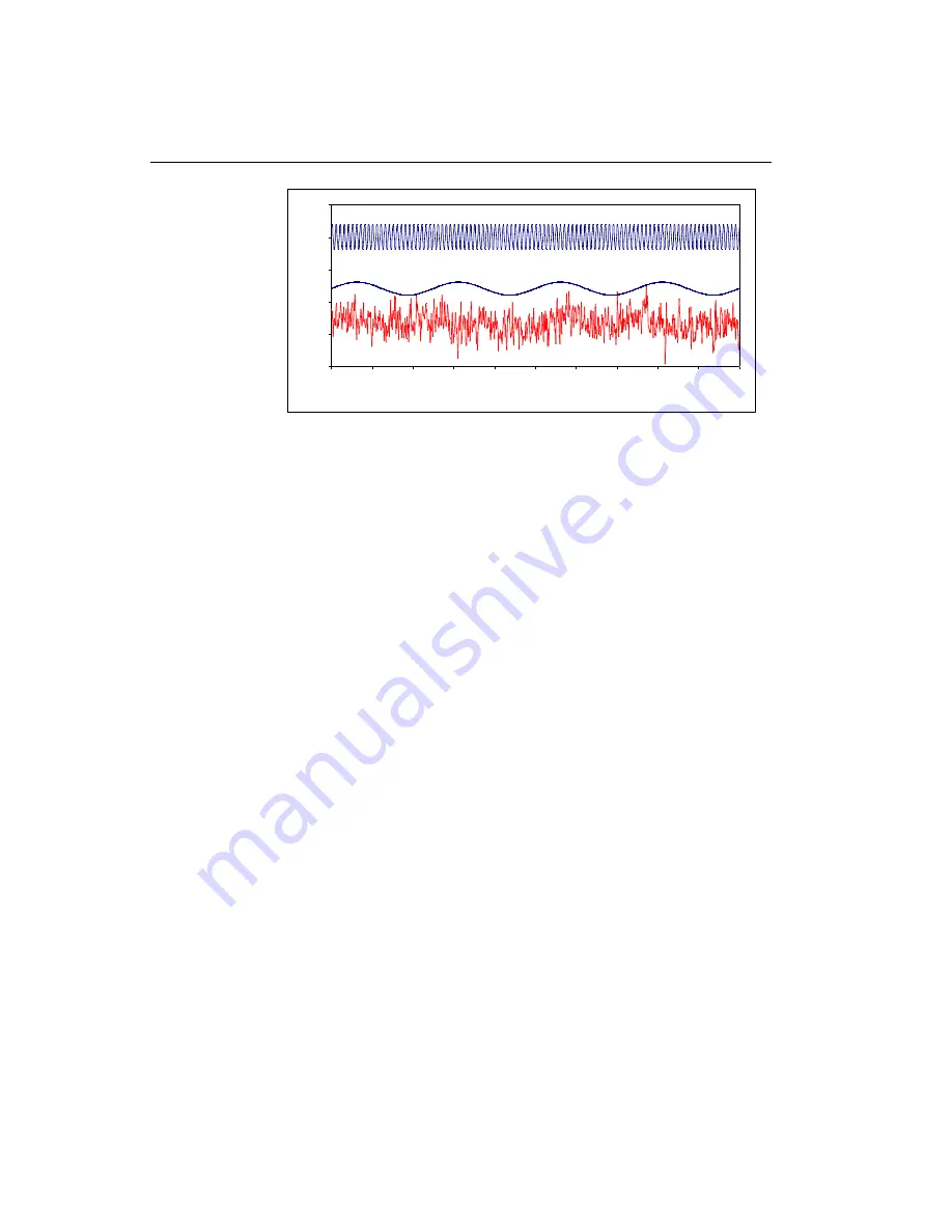
Fig. 23. Typical random noise in chromatography (lower trace). Both
frequencies (0.4 and 10 Hz) can be recognised amongst others.
Looking closely to the lower noise trace both frequencies (and others) can be
recognised. This is typical for noise in chromatography: a collection of more
or less random frequencies.
Low pass noise filters
The way noise filters work is by suppressing certain frequencies in the
acquired signal. Typically low pass filters allow chromatographic peaks (low
frequency) to pass, while high(er) frequency noise is attenuated. No matter
how advanced, it is impossible to use a low pass filter successfully if there is
no difference in frequency of signal and noise.
Analogue filters are made of hardware, from capacitors, resistors and
amplifiers (opamps). Digital filters are mathematical routines to process an
acquired signal.
Traditionally, in many detectors for chromatography an analogue low-pass
filter is applied (rise time filter). A ‘passive’ RC filter consists of resistors and
capacitors. An active higher order filter can be considered as a number of
these RC filters in series. In a 4
th
order filter the signal coming from the first
filter is filtered again in a second, third and fourth filter. During these steps,
loss of signal occurs simply because of all the resistors that are applied.
Operational amplifiers, which are ‘active’ components, are applied in each
stage to restore the signal to its original value.
With the availability of powerful processors, digital signal processing has
become an excellent alternative for hardware filters. In its most simple form a
running average filter takes the average of n data points to create a new data
point. For example in a 5-points running average filter output data point y[80]
is calculated from measured data points x[80]
– x[84] as:
-5
0
5
10
15
20
30
31
32
33
34
35
36
37
38
39
40
t (s)
I
(p
A
)
sine f = 10 Hz
sine f = 0.4 Hz
Summary of Contents for DECADE II 171
Page 12: ...12 DECADE II user manual ed 11...
Page 18: ...18 DECADE II user manual ed 11...
Page 32: ...32 DECADE II user manual ed 11...
Page 48: ...48 DECADE II user manual ed 11...
Page 54: ...54 DECADE II user manual ed 11...
Page 71: ...CHAPTER 8 Optimisation of working potential 71...
Page 72: ...72 DECADE II user manual ed 11...
Page 76: ...76 DECADE II user manual ed 11...