background image

 
Antaira Industrial Gigabit IEEE 802.11b/g/n Wireless 
APX-5700 User Manual V 1.0 


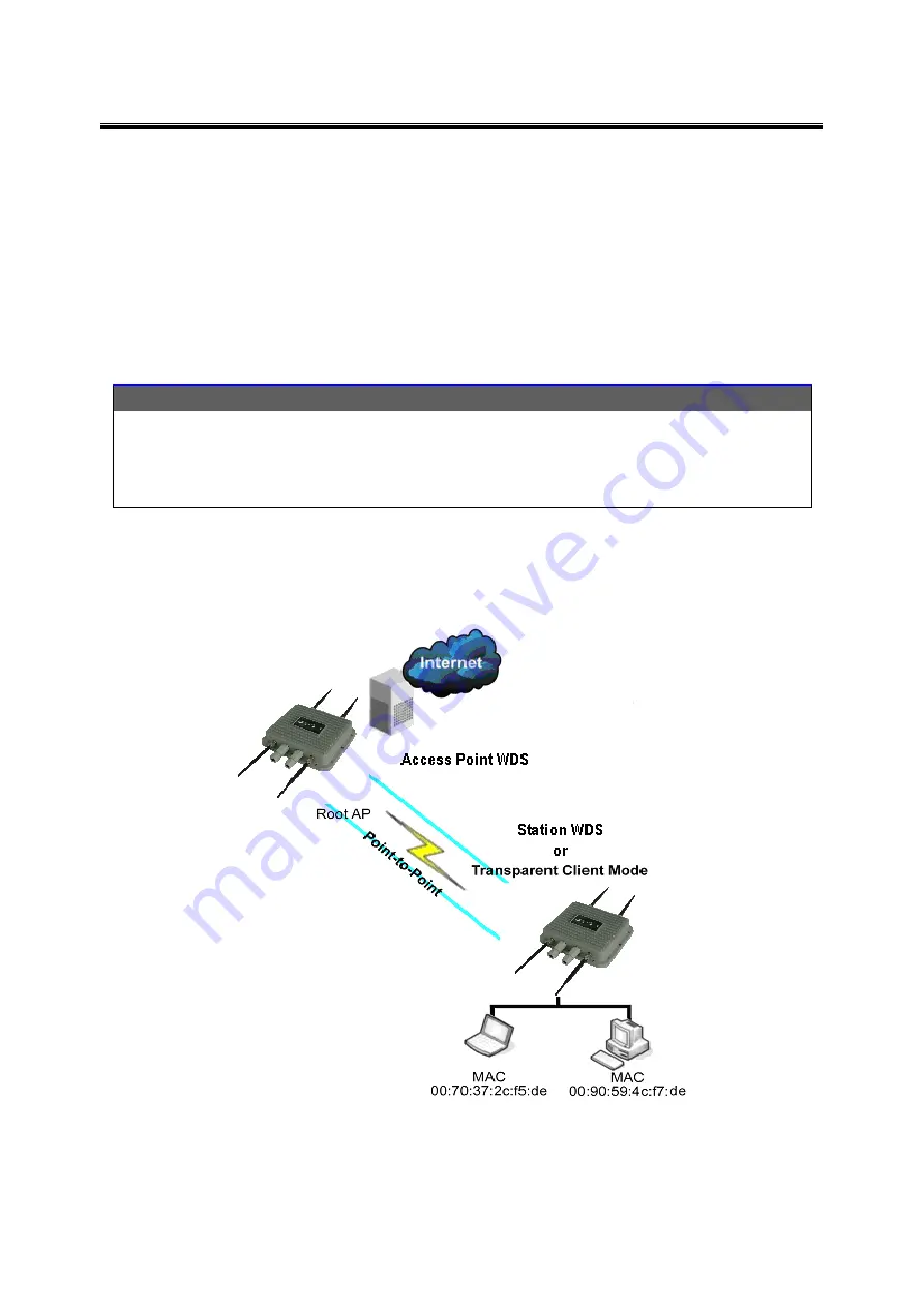
3.3 Station WDS Mode 


Station WDS mode is similar to Station mode. The difference is that Station WDS mode must be 

connected to an AP that is configured in Access Point WDS (or RootAP) mode. 

Station WDS is mainly used for a point-to

–point connection between two buildings or locations that are 

further away. 


Point-to-Point


Point-to-Multi-Point


An access point setup as Access Point WDS 

(or RootAP) and the other as Station WDS 

(Transparent Client). 

An access point setup as Access Point WDS (or 

RootAP) and several other devices as Station 

WDS (or Transparent Client). 


This mode is generally used for outdoor connections over long distances, or for indoor connections 

between local networks. 


Summary of Contents for APX-5700

Page 1: ...Antaira Industrial Gigabit IEEE 802 11b g n Wireless APX 5700 User Manual V 1 0 i APX 5700 Industrial IP67 Outdoor Gigabit IEEE802 11a b g n Wireless AP Client Bridge Repeater User Manual Version 1 0 ...

Page 2: ...otice Copyrights 2014 by Antaira Technologies LLC All rights reserved Reproduction adaptation or translation without prior permission of Antaira Technologies LLC is prohibited except as allowed under the copyright laws Disclaimer Antaira Technologies LLC provides this manual without warranty of any kind expressed or implied including but not limited to the implied warranties of merchantability and...

Page 3: ...the separation between the computer and receiver Consult the dealer or an experienced radio TV technician for help Caution Any changes or modifications not expressly approved by the grantee of this device could void the user s authority to operate the equipment CE Mark Warning This is a Class A product In a domestic environment this product may cause radio interference in which case the user may b...

Page 4: ...he R TTE Directive 1999 5 EC issued by the Commission of the European Community Compliance with this directive implies conformity to the following EMC Standards FCC 47 CFR Part 15 Subpart B 47 CFR Part 15 Subpart C Section 15 247 CE EN 300 328 2 EN 300 826 EN 301 489 17 Therefore this product is in conformity with the following regional standards FCC Class B following the provisions of FCC Part 15...

Page 5: ...e 7 3 3 Station WDS Mode 8 3 4 Repeater WDS Mode 9 4 Configure the IP Address 10 4 1 For Windows 95 98 98SE ME NT 10 4 2 For Windows XP 2000 11 5 Access the Web Interface 12 5 1 Access with uConfig 12 6 Access with Web Browser 14 7 Navigation 16 7 1 Status Page 17 7 1 1 Status Reporting 17 7 1 2 Clients Connection Status in AP Status Info 19 7 1 3 Station Connection Info 20 7 1 4 More Status 22 7 ...

Page 6: ... 7 6 1 Ping Watchdog 45 7 6 2 Auto Reboot 45 7 6 3 SNMP Setup 46 7 6 4 NTP Setup 46 7 6 5 Web HTTP Server 46 7 6 6 Telnet Access Setup 47 7 6 7 SSH Access Setup 47 7 6 8 System Log Setup 47 7 7 System Tab 48 7 7 1 Firmware Upgrade 48 7 7 2 Host Name 49 7 7 3 Administrative and Read Only Account 49 7 7 5 Configuration Management 50 7 7 6 Device Maintenance 50 7 8 VLAN Tab 51 7 8 1 VLAN Modes 51 VLA...

Page 7: ...eless applications The outdoor unit can be protected by utilizing the grounding plane that is conveniently located within the mounting bracket The APX 5700 series receives power though the Ethernet port and is a PoE Powered Device PD that conforms to the IEEE802 3af standard This series of outdoor wireless products has an operating temperature of 20 to 70 C To protect your security and privacy the...

Page 8: ...dard which is IEEE802 11i compliant The access point also supports IEEE 802 1x for a secure and centralized user based authentication Wireless clients are thus required to authenticate through highly secure methods like EAP TTLS and EAP PEAP in order to obtain access to the network uConfig Utility The uConfig utility allows users to access the user friendly web configuration interface of the acces...

Page 9: ...he connectors on the APX 5700 Port Description 10 100 1000 RJ 45 Gigabit Ethernet Ports 2 10 100 1000 Base T X RJ 45 Gigabit Ethernet port supports IEEE 802 3af PoE powered device Default Speed Auto ANT 1 2 N type connector for external antenna Front Panel of the APX 5700 Radio1 Antenna 1 Ethernet 1 Radio1 Antenna 2 Ethernet 2 Radio2 Antenna 1 Radio2 Antenna 2 ...

Page 10: ...le Mounting Each AP has a pole mounting kit on the rear panel The pole mounting kit helps to fix the AP in the appropriate location 2 2 2 Wall Mount Installation Each AP has another installation method to fix the AP A wall mount panel can be found in the package The following step shows how to mount the AP on a wall ...

Page 11: ...se a straight through cable to connect PC and AP The following table below shows the 10BASE T 100BASE TX MDI and MDI X port pin outs RJ 45 Pin Assignments Pin Number Assignment 1 TD 2 TD 3 RD 4 Not used 5 Not used 6 RD 7 Not used 8 Not used With 100BASE TX 10BASE T cable pins 1 and 2 are used for transmitting data and pins 3 and 6 are used for receiving data MDI MDI X Pin Assignments Note and sign...

Page 12: ...fault mode for the device It enables the bridging of wireless clients to wired network infrastructures and enables transparent access and communication with each other The illustration below shows a typical application when resources are sharing the same AP The wireless users are able to access the file server connected to the switch through the access point in AP mode This mode is generally used ...

Page 13: ...access point it creates a network link between the Ethernet network connected at the client device and the wireless Ethernet network connected at the access point In the example below the workgroup of PCs on the Ethernet network are connected to the station device which can access the printer across the wireless connection to the access point where the printer is connected ...

Page 14: ...DS is mainly used for a point to point connection between two buildings or locations that are further away Point to Point Point to Multi Point An access point setup as Access Point WDS or RootAP and the other as Station WDS Transparent Client An access point setup as Access Point WDS or RootAP and several other devices as Station WDS or Transparent Client This mode is generally used for outdoor co...

Page 15: ... over places which are generally difficult for wireless clients to connect to a network In repeater mode the AP acts as a relay for network signals on the network by regenerating the signals it receives and retransmitting them to the main network infrastructure Detailed information on the repeater mode is available in the Repeater Setup section Note Repeater WDS requires the AP to be setup in Root...

Page 16: ...work adapter that you are using then right click and select Properties S St te ep p 3 3 Highlight TCP IP and click on the Properties button S St te ep p 4 4 Select the Specify an IP address radio button Set the IP address to 192 168 168 X and subnet mask to 255 255 255 0 where X can be any number from 2 to 254 S St te ep p 5 5 To verify that the IP address has been correctly assigned to your PC go...

Page 17: ...P IP and click on the Properties button S St te ep p 4 4 Select the Use the following IP address radio button Set the IP address to 192 168 168 X and subnet mask to 255 255 255 0 where X can be any number from 2 to 254 S St te ep p 5 5 Click on the OK button to close all windows S St te ep p 6 6 To verify that the IP address has been correctly assigned to your PC go to the Start menu Accessories s...

Page 18: ...nf fi ig g icon to launch the utility then click Y Ye es s button S St te ep p 2 2 Select the access point from the products list and click on the O Op pe en n W We eb b button To retrieve and display the latest device s in the list click on the R Re ef fr re es sh h button S St te ep p 3 3 Do not exit the uConfig program while accessing the web based interface as this will disconnect you from the...

Page 19: ... 11b g n Wireless APX 5700 User Manual V 1 0 13 S St te ep p 4 4 At the login prompt enter the User Name and Password The default are User Name admin Password password S St te ep p 5 5 It then opens the device s home page the Status page ...

Page 20: ...S IE under the T To oo ol ls s tab select I In nt te er rn ne et t O Op pt ti io on ns s S St te ep p 2 2 Open the C Co on nn ne ec ct ti io on ns s tab and in the L LA AN N S Se et tt ti in ng gs s section disable all the option boxes Click on the O OK K button to update the changes S St te ep p 3 3 At the A Ad dd dr re es ss s bar type in http 192 168 168 1 and press E En nt te er r on your keyb...

Page 21: ...E 802 11b g n Wireless APX 5700 User Manual V 1 0 15 S St te ep p 4 4 At the login prompt enter the User Name and Password The default are User Name admin Password password Step 5 It then opens the device s home page the Status page ...

Page 22: ... See Advanced Network page settings for more details Services Page covers the configuration of system management services i e Ping Watchdog Auto Reboot SNMP NTP Telnet SSH System Log System Page contains controls for system maintenance routines administrator account management device customization and configuration backup How to Save Changes After changes have been made from each respective setup ...

Page 23: ...etrieved from the internet services using Network Time Protocol NTP only if the device is setup and connected to the internet otherwise the date and time update will be from the device s inaccurate autonomous clock Version Firmware Version Displays current firmware version in operation Loader Version Displays current loader version of the device LAN Setting LAN MAC Displays the MAC address of the ...

Page 24: ...ry DNS IP address of the WAN setting WAN Sec DNS IP Displays the secondary DNS IP address of the WAN setting Radio Wireless Mode Displays the current operating mode of the device Local AP SSID Displays the current Service Set Identifier SSID of the device when it operates in access point mode Frequency Displays current operating frequency running in the device WLAN MAC Displays the MAC address or ...

Page 25: ...the AP can be viewed from the AP Status page The following images are an example of a client s connection status info Click to refresh the client connection statistics and status page The signal strength at the left and right port of the radio card can be viewed more accurately when the antenna is adjusted which will help to acquire a more balanced reception ...

Page 26: ... the data rate and consequently the higher the data throughput will be Channel Width HT20 indicates established connection is 20MHz channel width o HT40 indicates established connection is 40MHz channel width WLAN Local AP Statistics Bytes transmitted received value represents the total amount of data in bytes transmitted and received during connection WLAN Local AP Errors This section displays th...

Page 27: ...on These packets were dropped due to re assembling failure as some link layer fragments of the packet were lost Tx Excessive Retries value represents the number of packets which failed to be delivered to the destination Undelivered packet are retransmitted a number of times before an error occurs Missed Beacons value represents the number of beacons management packets sent at regular intervals by ...

Page 28: ...eful tools specifically for the status pages Ping Utility Use the ping tool to test the connectivity between devices ARP Table displays a list of MAC addresses of the connected devices Bridge Table displays a list of devices connected to a bridge interface DHCP Active Lease Table displays a list of IP addresses leased to all computers ...

Page 29: ...pecific IP address for the device o Default IP address is 192 168 168 1 DHCP Client When setup this allows the device to learn the IP address automatically from the network Netmask Allows the user to set the class for the IP address set o Default class C and value is 255 255 255 0 Gateway Optional Enter the gateway IP address of the network for the connected device Primary DNS IP Optional Enter th...

Page 30: ...he IP class for the IP address range set for the start and end address Note If the device is also the router then the IP class must be the same as the device IP class DHCP Lease Time Enter the new lease time in seconds default is 3600 seconds or 1 hour DHCP Server Relay IP Enter the IP address of the remote DHCP server where the DHCP client request will be relayed to get the IP address DHCP Gatewa...

Page 31: ...e Ensure the device s gateway IP is also set to allow devices to access the internet Primary DNS IP Optional Enter the primary DNS IP address nearest the gateway router Secondary DNS IP Optional Enter the secondary DNS IP address nearest the gateway router Bandwidth Control Between Ethernet and Wireless An entry value of 0 means there is no bandwidth flow which limits communication between the two...

Page 32: ...e or disable the radio Basic Wireless Settings All the basic wireless settings can be configured using the information on this page Operators can change the ESSID regulatory country code wireless profile channel spectrum width frequency of interest data rates transmit power and rate aggressiveness 7 3 1 Wireless Mode There are 5 modes available 1 Access Point This mode can be connected to the stat...

Page 33: ...enables packet forwarding at the layer 2 level Unlike station mode it is fully transparent at layer 2 level Note For Station WDS Access Point WDS Repeater WDS WDS protocol used is not defined as the standard thus compatibility issues between equipment from different vendors might arise 5 Repeater WDS This mode consists of a station WDS and an access point WDS mode The repeater WDS must first link ...

Page 34: ...d and represents a mixed of 802 11n and 802 11a mode NG is 11n 2 4GHz band and represents a mixed of 802 11n 802 11g and 802 11b mode Channel Spectrum Width The 20M represents the data transmitted at a bandwidth of 20MHz 20 40MHz and represents the data transmitted at either 20MHz or 40MHz In a noisy environment it automatically falls back to 20MHz in order to be more resilient to the interference...

Page 35: ...wer level low will remain unchanged The user then needs to readjust the power level in order to take advantage of the higher power output available for the channel Rate Aggressiveness This allows users to reduce or increase the transmit rate while still remaining in full auto algorithm There are two scenarios when rate aggressiveness is useful First the environment might be noisy at times so one w...

Page 36: ... will need to set security parameters in the wireless security section Click Scan to re scan the access points in range Select the access point from the list and click Close This Window The site survey channel scan list can be modified using the channel scan control list Remote AP Lock to MAC Enter the MAC address of the remote access point the device is connected to This option will only make the...

Page 37: ...z band and represents a mixed of 802 11n 802 11g and 802 11b mode Station setting must match the AP Wireless Profile setting Channel Spectrum Width The 20M represents the data transmitted at a bandwidth of 20MHz and the 20 40MHz represents the data transmitted at either 20MHz or 40MHz In a noisy environment it automatically reverts back to 20MHz in order to be more resilient to the interference In...

Page 38: ...col TKIP which uses an RC4 encryption algorithm AES Advanced Encryption Standard AES algorithm AUTO Default Automatically selects between both algorithms Pre Shared Key This option is available when WPA or WPA2 is selected in addition to the selection of PSK The pre shared key is an alpha numeric password between 8 and 63 characters long Important An 802 11n network using WPA authentication should...

Page 39: ...on Standard AES algorithm AUTO Default Automatically selects between both algorithms Primary Radius Server IP Enter the primary radius server IP address Secondary Radius Server IP Enter the secondary radius server IP address Authentication Port Enter the authentication port number of the radius server The default is 1812 Accounting Port Enter the accounting port number of the radius server The def...

Page 40: ...thentication User Name Identification credential used by the WPA supplicant for EAP tunneled authentication in an unencrypted form User Password The password credential used by the WPA supplicant for the EAP authentication IEEE802 1x Settings The operations of the keys are the same for ALL the modes Note Operating with IEEE802 1x security will limit the AP to a maximum wireless link speed of only ...

Page 41: ...n The default is 1812 Accounting Port Enter the radius server accounting port that will be used The default is 1813 Radius Secret Key Enter the radius server secret key that the access point will use to authenticate itself with the radius server IEEE802 1x Key Rotation For higher security enter the time in seconds it takes before the key rotation is activated in the authentication process IEEE802 ...

Page 42: ...EP security method is used The 128 bit option will provide a higher level of security o For 64 bit specify the WEP key as 5 HEX 0 9 A F or a f pairs e g 00112233AA or 5 ASCII characters o For 128 bit specify the WEP key as 13 HEX 0 9 A F or a f pairs e g 00112233445566778899AABBCC or 13 ASCII characters 7 3 5 Virtual Access Point VAP Virtual AP VAP implements Multi SSID mSSID whereby a single wire...

Page 43: ...eration for environmental conditions which can help to achieve the best performance and better link reliability Noise Immunity Check the box to enable this setting When enabled it automatically adjusts the signal noise level for the best performance In low noise environments it is recommended to turn off this function Station Isolation When enabled this can help prevent wireless clients on the sam...

Page 44: ...s APX 5700 User Manual V 1 0 38 7 5 Advanced Network Tab Click the Advanced Network tab from the menu to open the page below Note This tab will not open when the device is in bridge mode To open the page first enable the router mode in the basic network ...

Page 45: ...Default is disabled Check on the box to enable DMZ IP Address Input the IP address of the local PC to receive the DMZ packets Port Forwarding Default is disabled Check on the box to enable For configuration refer to the Appendix section Adding an Entry from Known Server To add an entry use the box pictured above and then select an application from the list Server Type Click to select the wanted ap...

Page 46: ... leave blank If port range enter last port number here Private IP Address Enter the local IP of the PC running the application Private Port From If single port enter same public port number or new port number If port range enter only the starting port number Public IP Address If the application is to allow anyone access on the internet then select the default All If only a specific IP is allowed i...

Page 47: ...ddress and Netmask The source IP of the packet specified within the packet header is usually the IP of the host system which sends the packets Src Port Enter the source port number in the rule check The source port of the TCP UDP packet specified within the packet header is usually the port of the host system application which sends the packets Destination IP Mask Enter the destination IP and Netm...

Page 48: ... Dynamic DNS Setup Default is disabled Check on box to enable The dynamic DNS allows the router s WAN dynamic IP address to be linked and automatically updated to the domain server which hosts the service every time the IP address is changed This ensures that the users on the internet can always have access to the hosting service behind the router For configuration refer to the Appendix section 7 ...

Page 49: ... disabled Check on box to enable When enabled the client PC running Microsoft UPnP services can automatically open a specific port required by the PC application in the router For security reasons this service should not be open It is recommended to manually setup all open port services through Port Forwarding ...

Page 50: ...802 11b g n Wireless APX 5700 User Manual V 1 0 44 7 6 Services Tab Click the Services tab from the menu to open the page below The services section provides a variety of useful and enhanced functions to help assist device operations ...

Page 51: ...fter the device s startup Failed Count to Reboot The device has a default fail count of 5 This is the number of ping failures before the device kicks into the reboot process 7 6 2 Auto Reboot Auto Reboot Mode Default is disabled Select By Hour or By Time Auto reboot mode allows the user to preset a timer to automatically force a reboot The timer can be a fixed number of hours or a specified time o...

Page 52: ...is triggered Community Enter the SNMP community string 7 6 4 NTP Setup Enable NTP Client Default is disabled Check on the box to enable Select Your Time Zone Select the country from the list where the user resides Custom Time Server Default is time nist gov Enter the preferred time server domain IP Known Time Server The user can select one option from the list as the new time server 7 6 5 Web HTTP...

Page 53: ...rred port number 7 6 7 SSH Access Setup Enable SSH Server Default is disabled Check on the box to enable Server Port Default is 22 If necessary enter a new and preferred port number 7 6 8 System Log Setup Enable System Logging Default is disabled Check on the box to enable Logging IP Domain Name Enter the destination IP address of the device that is supposed to receive the log Logging Port Default...

Page 54: ... if activated Current Firmware Displays device s version of firmware that is currently operating Firmware File Activates the Browse button that navigates to the new firmware file The full path to the new firmware file location can be seen there The new firmware file is then transferred to the system after the upload button is activated The upgrade button should be activated in order to proceed wit...

Page 55: ...d configuration The default administrator s password should be changed on the very first system setup Administrator Username Specifies the name of the system user Current Password Administrator is required to enter a current password It is required that the password or administrator username is routinely changed to ensure your security Default Administrator Login Credentials User Name admin Passwo...

Page 56: ...tions from different types of devices 7 7 6 Device Maintenance The controls in this section are dedicated for the device maintenance routines rebooting resetting and generating the supportive informational report Reboot Activate the Reboot control in order to initiate a full reboot cycle of the device The reboot effect is the same as the hardware reboot which is similar to the power off power on c...

Page 57: ...s SSID type in the ID number select Tag and click Add To add a Tag VLAN ID for VAP1 wireless SSID type in the ID number select Tag and click Add To add a Tag VLAN ID for VAP2 wireless SSID type in the ID number select Tag and click Add To add a Tag VLAN ID for VAP3 wireless SSID type in the ID number select Tag and click Add Warning Adding a Tag VLAN ID to the device s interface port can cause a l...

Page 58: ...a VLAN ID of 2001 with a masquerade IP address of 192 168 168 20 Another entry is in the VLAN management and has a VLAN ID of 2002 with a masquerade IP address of 192 168 168 10 The user can only select one of the two entries in order to be the active VLAN ID and IP address If the VLAN ID 2001 group is selected only computers in that VLAN ID group can open the AP device web page using the IP addre...

Page 59: ...ll settings can be configured for Layer 2 packet filtering and access control in bridge mode Router operating mode can be configured to operate in Layer 3 to perform routing and to enable network segmentation wireless clients will be on different IP subnets Router mode will block broadcasts as it is not transparent The device supports multicast packets to pass through in router mode The router can...

Page 60: ... Class C networks Gateway IP Typically this is the IP address of the host router that provides the point of connection to the internet This can be a DSL modem cable modem or a WISP gateway router The device will direct the packets of data to the gateway if the destination host is not within the local network The gateway IP address should be from the same address space on same network segment as th...

Page 61: ... packets Destination IP mask is the destination IP of the packet specified within the packet header which is usually the IP of the system which the packet is addressed to Destination Port is the destination port of the TCP UDP packet specified within the packet header which is usually the port of the host system application in which the packet is addressed to Comments are the informal field of a p...

Page 62: ...eway IP for all the devices connected on the internal network The IP address will also be used for management purposes of the device WLAN IP Address This IP address represents the LAN or WLAN interface that is connected to the external network according to the wireless operation mode described above It is the IP address that can be used for routing and device management purposes The external netwo...

Page 63: ... interface IP address and then sub routed to other client devices residing on its local network while the device is operating in AP AP WDS wireless mode and in the contrariwise direction in Station or Station WDS mode NAT is implemented using the masquerade type firewall rules NAT firewall entries are stored in the IP tables and NAT tables while the device is operating in router mode Please refer ...

Page 64: ...or disable a particular port forwarding entry All the added firewall entries are saved in a system configuration file however only the enabled port forwarding entries will be active during the system s operation New entries in port forwarding can be saved by activating the Save button or can be discarded by activating the Cancel button in the port forwarding configuration window DNS Proxy The DNS ...

Page 65: ...ption PPPoE to configure a PPPoE tunnel in order to connect to an ISP Only the external network interface can be configured as a PPPoE client and all the traffic will be sent via this tunnel The IP address default gateway IP and DNS server IP address will be obtained from the PPPoE server after the PPPoE connection is established The broadcast address is used for the PPPoE server discovery and tun...

Page 66: ...nd address it to a group of computers that want to receive it This technique addresses packets to a group of receivers rather than to a single receiver It depends on the network to forward the packets to the hosts that need to receive them Common routers tend to isolate all the broadcast thus multicast traffic between the internal and external networks however this provides the multicast traffic p...

Page 67: ...e the full auto algorithm might give low throughput so increase the rate aggressiveness and it will increase the transmit rate and in this case will have a higher throughput Choose a range of value from 3 2 1 Noise Immunity options increases the robustness of the device to operate in the presence of noise disturbance which is usually generated by external 802 11 traffic sources channel hopping sig...

Page 68: ... outdoor links The user also has the ability to manually enter the value Distance This specifies the distance value in miles or kilometers by using a slider or you can manually enter the value The signal strength and throughput falls off with range Changing the distance value will change the ACK timeout to the new and appropriate distance value ACK Timeout Every time the station receives a data fr...

Page 69: ...e replies If the specified number of ICMP echo response packets is not continuously received the ping watchdog tool will reboot the device SNMP Agent Simple Network Monitor Protocol SNMP is used in network management systems to monitor network attached devices for conditions that warrant administrative attention The device contains an SNMP agent that allows it to communicate to SNMP management app...

Page 70: ...rver parameters can be set Enable SSH Server Enables SSH access to the device Server Port SSH service TCP IP port setting System Log Enable Log This option enables the registration routine of the system log messages Enabling the remote log enables the syslog to remotely send the function while the system log messages are sent to a remote server specified by the remote log IP address and remote log...

Page 71: ...Antaira Industrial Gigabit IEEE 802 11b g n Wireless APX 5700 User Manual V 1 0 65 Appendix V VLAN Setup Examples A Tagged Wireless VLAN to Tagged Ethernet VLAN Setup ...

Page 72: ...gh Antaira Customer Service and Support Antaira US Headquarter 844 268 2472 Antaira Europe Office 48 22 862 88 81 Antaira Asia Office 886 2 2218 9733 Please report any problems to Antaira www antaira com support antaira com www antaira eu info antaira eu www antaira com tw info antaira com tw Any changes to this material will be announced on the Antaira website ...

Reviews: