Anritsu 3659 User Manual Download Page 20

2-5 Running the Verification Software

Using the 2300-580-R Software with VectorStar ME7838D

2-8

PN: 10410-00327  Rev. D

3659 0.8 mm Cal/Ver Kit & 2300-580-R PVS UG

Enter Port 2 BB/mm-Wave Module Information
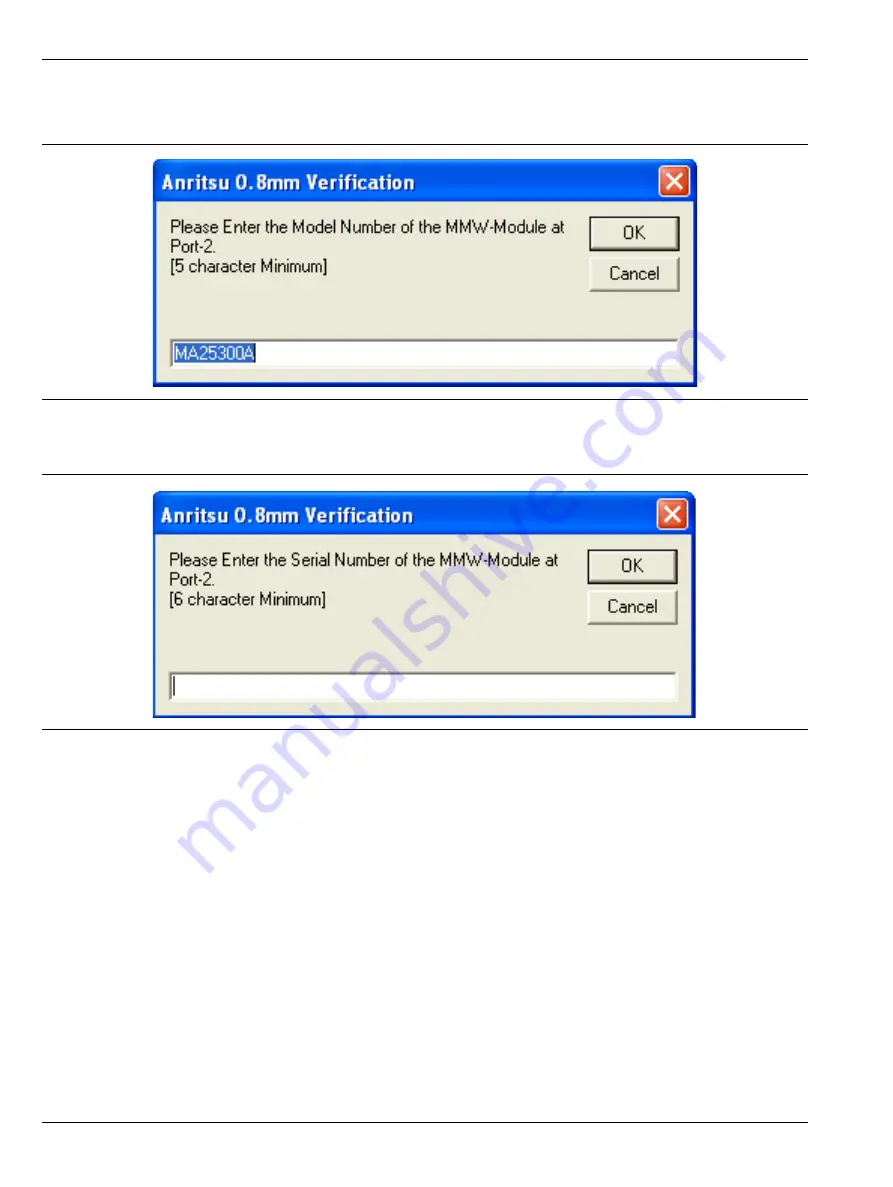
12. 

Enter the Port 2 BB/mm-Wave Module model number and click 

OK

.

13. 

Enter the Port 2 BB/mm-Wave Module serial number and click 

OK

.

Figure 2-10.

Anritsu 0.8 mm Verification Dialog – Port 2 BB/mm-Wave Module – Model Number

Figure 2-11.

Anritsu 0.8 mm Verification Dialog – Port 2 BB/mm-Wave Module – Serial Number

Summary of Contents for 3659

Page 1: ...orStar ME7838D4 Modular Broadband Millimeter Wave VNA System with 3739C BB Test Set and MA25300A mm Wave Modules VectorStar ME7838G Modular Broadband Millimeter Wave VNA System with MA25400A mm Wave M...

Page 2: ......

Page 3: ...ation Compliance and Safety 1 4 Chapter 2 Using the 2300 580 R Software with VectorStar ME7838D 2 1 Introduction 2 1 2 2 Required Equipment 2 1 Required VectorStar ME7838D Broadband System 70 kHz to 1...

Page 4: ...for Alternate Frequency Band 2 35 Procedure 2 35 2 15 Troubleshooting 2 36 Difficulty Running the Program 2 36 Difficulty Meeting System Specifications 2 36 Chapter 3 Using the 2300 580 R Software wi...

Page 5: ...t Cal 3 28 Save Data 3 28 Matched Thru 3 28 Matched Thru SN 3 28 Mismatched Thru 3 28 Mismatched Thru SN 3 28 3 10 Application Interface Serial Number Tab Functions 3 29 3 11 Matched Thru Tests Port 1...

Page 6: ...smatched Thru Tests Port 3 Port 4 3 53 Procedure 3 53 3 22 Saving Verification Data 3 56 3 23 Restart for Alternate Frequency Band 3 56 Procedure 3 56 3 24 Troubleshooting 3 57 Difficulty Running the...

Page 7: ...Functions 4 29 4 11 Matched Thru Tests 4 30 Procedure 4 30 4 12 Mismatched Thru Tests 4 32 Procedure 4 33 4 13 Saving Verification Data 4 36 4 14 Restart for Alternate Frequency Band 4 36 Procedure 4...

Page 8: ...2300 580 R PVS UG Table of Contents Continued 6 4 Making a Connection 6 6 Before Connection 6 6 Initial Connection 6 6 Torquing the Connection 6 8 Torque Specifications and Tools 6 9 Disconnection 6...

Page 9: ...VNA System VectorStar ME7838D4 Series Modular BB mm VNA System VectorStar ME7838G Series Modular BB mm VNA System using this kit to 145 GHz The components in this kit provide the basis for issuing a c...

Page 10: ...ru High dat GPIB Interface Card and Cable Depending upon the Operating System and hardware used to perform the verification there are different requirements for the GPIB hardware configurations This s...

Page 11: ...850 2 Male Open 24 850 3 Male Offset Short 3 23 850 3 4 Male Offset Short 2 23 850 2 5 Male Offset Short 1 23 850 1 6 Female Broadband Termination 28 8F50 7 Female Open 24 8F50 8 Female Offset Short...

Page 12: ...mponent Name and Description Anritsu Part Number 16 0 8 Male Female Adapter 33 8 8F50 17 0 8 Male Male Adapter 33 8 850 20 Stepped Impedance Mismatch Thru Line Verification Device inside plastic box 1...

Page 13: ...nect cables between the test set and the VNA Necessary front panel interconnect cables between the test set and the VNA Necessary interconnect cables to the MA25300A mm Wave Modules 2 3 Configuring th...

Page 14: ...on software the National Instruments GPIB card and its drivers must be installed in the PC Controller 2 Turn off all other running applications on the PC Controller 3 Insert the USB drive into the PC...

Page 15: ...8 mm Cal Ver Kit 2300 580 R PVS UG PN 10410 00327 Rev D 2 3 8 Two installation wizard setup dialog boxes appear in sequence Click Next to proceed through each dialog box The final dialog box shows an...

Page 16: ...x appears Click Next and the Installation Complete dialog box appears 10 The installer adds all required files and makes the necessary registry updates on the PC Controller When done the navigation pa...

Page 17: ...mm Module Model number and serial number of the Port 2 BB mm Module Procedure 1 With the equipment and software configured as described in Configuring the Hardware on page 2 1 turn on the computer an...

Page 18: ...the VNA is found a confirmation dialog box appears 8 Click Yes to continue or click No to search for another VNA 9 If Yes is clicked above the program searches for the BB mm Modules and when found re...

Page 19: ...Rev D 2 7 Enter Port 1 BB mm Wave Module Information Enter the Port 1 BB mm Wave Module model number and click OK 11 Enter the Port 1 BB mm Wave Module serial number and click OK Figure 2 8 Anritsu 0...

Page 20: ...PVS UG Enter Port 2 BB mm Wave Module Information 12 Enter the Port 2 BB mm Wave Module model number and click OK 13 Enter the Port 2 BB mm Wave Module serial number and click OK Figure 2 10 Anritsu...

Page 21: ...on 14 Enter the Test Set model number and click OK 15 Enter the Test Set serial number found on the rear panel and click OK 16 The program execution continues to the following Section 2 6 Application...

Page 22: ...Menu tab display is described in Section 2 9 Application Interface Main Menu Tab on page 2 24 The Serial Number Info tab is described in Section 2 10 Application Interface Serial Number Tab Functions...

Page 23: ...s into the VNA then click OK 6 The VNA displays an acknowledgment dialog box when the file load is complete indicating that 10 files were loaded After the VNA has loaded the 10 Calibration coefficient...

Page 24: ...a In the Frequency Range area select either the low range 40 MHz to 80 GHz or the high range 80 GHz to 145 GHz For purposes of this document the low band is done first The range that is not selected i...

Page 25: ...l Ver Kit 2300 580 R PVS UG PN 10410 00327 Rev D 2 13 8 Select the 0 8 mm Coax type and then the Verification Kit Serial Number usually the same as the Calibration Kit When the Serial Number is comple...

Page 26: ...it Data Path text field In rare instances due to PC USB configurations the Auto find function may not be able to locate the verification data on the USB drive In this case you may need to use the Manu...

Page 27: ...ere is a file named EnableKit dat Double click that file to identify the file This builds the path for the verification kit data and returns back to the Find Verification Kit Data on the removable USB...

Page 28: ...16 PN 10410 00327 Rev D 3659 0 8 mm Cal Ver Kit 2300 580 R PVS UG 11 Click Verify Files on USB Drive The application checks the files on the USB drive to verify that all files are present and that ea...

Page 29: ...and you are ready to start click the Setup Calibration of VNA button A confirmation dialog box appears 13 Click Yes to start Click No to stop the calibration 14 The program execution continues in eit...

Page 30: ...hort Short Short Thru calibration Procedure 1 The 0 8 mm Verification Install Adapter dialog box appears a Install a F F adapter on VNA Port 1 so that a Female connector is available to the operator b...

Page 31: ...al Kit Broadband Load Device to VNA Port 1 b Connect the Female Broadband Load Device to VNA Port 2 c When ready to proceed click OK 4 The VNA measures the broadband load device data then the VNA Cali...

Page 32: ...2 c When ready to proceed click OK 6 The VNA measures the short open device data then the VNA Calibration Step 5 of 5 dialog box appears a Remove the Short and the Open from Port 1 and Port 2 respect...

Page 33: ...d Thru calibration Procedure 1 The 0 8 mm Verification Install Adapter dialog box appears a Install a F F adapter on VNA Port 1 so that a Female connector is available to the operator b Install a F M...

Page 34: ...ation Step 3 of 5 dialog box appears a Connect the Male 1 63 mm Short 2 to VNA Port 1 b Connect the Female 2 06 mm Short 3 to VNA Port 2 c When ready to proceed click OK 5 The VNA Calibration Step 4 o...

Page 35: ...2 23 a Remove the offset Shorts from Port 1 and Port 2 b Slide the two T R modules towards each other and connect the VNA Port 1 Female to VNA Port 2 Male directly c When ready to proceed click OK 7...

Page 36: ...cation Interface Setup Menu Tab on page 2 10 The Main Menu tab display is described in the section immediately following and is shown below in Figure 2 35 The Serial Number tab is described in Section...

Page 37: ...the VNA has finished a sweep the program auto scales all four channels before continuing The VNA display during the calibration and verification tests is set to one Channel and four traces Each trace...

Page 38: ...is in Local Lock Out unless this button is pushed This prevents an inadvertent front panel button actuation from affecting the proper operation of the program Restart Button The Restart button comman...

Page 39: ...command button writes data files to the PC GPIB Controller and stores the files at C mmdcsvc Data The program does not write data to the verification kit USB memory device If selected program executi...

Page 40: ...Application Interface Serial Number Tab Functions The Serial Number Info tab displays a summary of the model number and serial number for the following devices All screen information is included in t...

Page 41: ...Serial Number Match Thru dialog box appears 2 Ensure that the correct device is connected The Matched Thru verification standard is the device with one scribe line The Mismatched Thru verification sta...

Page 42: ...it 2300 580 R PVS UG 6 Connect the Matched Thru female connector to VNA Port 2 7 When ready to proceed click OK The matched thru test starts and the Matched Thru Test Sweep 1 dialog box appears After...

Page 43: ...ace Main Menu Tab on page 2 24 The dialog box is shown in Figure 2 35 ME7838D Application Interface Main Menu Tab on page 2 24 above 10 If the Run All Tests button was selected the program execution c...

Page 44: ...u button was selected above program execution starts here If the Run All Tests button was selected above program execution continues here after the Matched Thru tests described above in Section 2 11 M...

Page 45: ...ru Airline dialog box appears 4 Connect the Mismatched Thru Airline male connector to VNA Port 1 with the device label facing up 5 Connect the Mismatched Thru Airline female connector to VNA Port 2 6...

Page 46: ...menu described Section 2 9 Application Interface Main Menu Tab on page 2 24 above and the display should look similar to Figure 2 46 below This is a typical display immediately after measuring the Mis...

Page 47: ...tched Thru tests have been successfully completed and the data saved it is necessary to restart the program and test the other frequency band For example if you tested for 40 MHz to 80 GHz Frequency R...

Page 48: ...fication procedure 19 The program returns to the main menu described in Section 2 9 Application Interface Main Menu Tab on page 2 24 2 15 Troubleshooting Difficulty Running the Program If you have dif...

Page 49: ...UG PN 10410 00327 Rev D 2 37 5 Assure all active systems have been powered on at least one hour before the start of the calibrations If you still have difficulty after following the above steps please...

Page 50: ...2 15 Troubleshooting Using the 2300 580 R Software with VectorStar ME7838D 2 38 PN 10410 00327 Rev D 3659 0 8 mm Cal Ver Kit 2300 580 R PVS UG...

Page 51: ...ecessary rear panel interconnect cables between the test set and the VNA Necessary front panel interconnect cables between the test set and the VNA Necessary interconnect cables to the MA25300A mm Wav...

Page 52: ...on software the National Instruments GPIB card and its drivers must be installed in the PC Controller 2 Turn off all other running applications on the PC Controller 3 Insert the USB drive into the PC...

Page 53: ...0 8 mm Cal Ver Kit 2300 580 R PVS UG PN 10410 00327 Rev D 3 3 8 Two installation wizard setup dialog boxes appear in sequence Click Next to proceed through each dialog box The final dialog box shows a...

Page 54: ...ox appears Click Next and the Installation Complete dialog box appears 10 The installer adds all required files and makes the necessary registry updates on the PC Controller When done the navigation p...

Page 55: ...ave Test Set Model number and serial number of the Port 1 BB mm Module Model number and serial number of the Port 2 BB mm Module Procedure 1 With the equipment and software configured as described in...

Page 56: ...f Yes is clicked in Step 8 the program searches for the BB mm Modules and when found requests the model number and the serial number of the test set and each module 10 The ME7838D4 is a 4 port system...

Page 57: ...proceed with the steps in this section If testing ports 3 and 4 proceed to Enter Port 3 BB mm Wave Module Information on page 3 9 1 Enter the Port 1 BB mm Wave Module model number and click OK 2 Ente...

Page 58: ...R PVS UG Enter Port 2 BB mm Wave Module Information 3 Enter the Port 2 BB mm Wave Module model number and click OK 4 Enter the Port 2 BB mm Wave Module serial number and click OK Figure 3 10 Anritsu...

Page 59: ...proceed with the steps in this section If testing ports 1 and 2 proceed to Enter Test Set Information for All Ports on page 3 11 1 Enter the Port 3 BB mm Wave Module model number and click OK 2 Enter...

Page 60: ...Module Information 3 Enter the Port 4 BB mm Wave Module model number and click OK 4 Enter the Port 4 BB mm Wave Module serial number and click OK 5 Continue to Enter Test Set Information for All Ports...

Page 61: ...Set model number for Ports 1 and 2 and click OK 2 Enter the Test Set serial number for Ports 1 and 2 found on the rear panel and click OK 3 Enter the Test Set model number for Ports 3 and 4 and click...

Page 62: ...ev D 3659 0 8 mm Cal Ver Kit 2300 580 R PVS UG 4 Enter the Test Set serial number for Ports 3 and 4 found on the rear panel and click OK 5 The program execution continues as shown in Section 3 6 Appli...

Page 63: ...s described in this section The Main Menu tab display is described in Section 3 9 Application Interface Main Menu Tab on page 3 25 The Serial Number Info tab is described in Section 3 10 Application I...

Page 64: ...ling the 3659 calibration coefficients into the VNA then click OK 6 The VNA displays an acknowledgment dialog box when the file load is complete indicating that 10 files were loaded After the VNA has...

Page 65: ...a In the Frequency Range area select either the low range 40 MHz to 80 GHz or the high range 80 GHz to 145 GHz For purposes of this document the low band is done first The range that is not selected i...

Page 66: ...0 R PVS UG 8 Select the 0 8 mm Coax type and then the Verification Kit Serial Number usually the same as the Calibration Kit When the Serial Number is complete the Locate USB Drive Kit Data on PC area...

Page 67: ...button This utility allows you to manually select the path where the verification kit data is located The data path will be on the USB drive shipped with the verification kit On most PC s this will be...

Page 68: ...NA button A confirmation dialog box appears 13 Click Yes to start Click No to stop the calibration 14 If Port1 Port2 is requested the program execution continues in either Section 3 7 Low Band Calibra...

Page 69: ...a full 12 term SSST Short Short Short Thru calibration Procedure 1 The 0 8 mm Verification Install Adapter dialog box appears a Install a F F adapter on VNA Port 1 so that a Female connector is availa...

Page 70: ...e Male Cal Kit Broadband Load Device to VNA Port 1 b Connect the Female Broadband Load Device to VNA Port 2 c When ready to proceed click OK 4 The VNA measures the broadband load device data then the...

Page 71: ...Port 2 c When ready to proceed click OK 6 The VNA measures the short open device data then the VNA Calibration Step 5 of 5 dialog box appears a Remove the Short and the Open from Port 1 and Port 2 res...

Page 72: ...m SOLT Short Open Load Thru calibration Procedure 1 The 0 8 mm Verification Install Adapter dialog box appears a Install a F F adapter on VNA Port 1 so that a Female connector is available to the oper...

Page 73: ...A Calibration Step 3 of 5 dialog box appears a Connect the Male 1 63 mm Short 2 to VNA Port 1 b Connect the Female 2 06 mm Short 3 to VNA Port 2 c When ready to proceed click OK 5 The VNA Calibration...

Page 74: ...580 R PVS UG a Remove the offset Shorts from Port 1 and Port 2 b Slide the two T R modules towards each other and connect the VNA Port 1 Female to VNA Port 2 Male directly c When ready to proceed clic...

Page 75: ...ace Setup Menu Tab on page 3 13 The Main Menu tab display is described in Section 3 9 Application Interface Main Menu Tab on page 3 25 and is shown in Figure 3 39 The Serial Number tab is described in...

Page 76: ...cts the VNA has finished a sweep the program auto scales all four channels before continuing The VNA display during the calibration and verification tests is set to one Channel and four traces Each tr...

Page 77: ...ent is in Local Lock Out unless this button is pushed This prevents an inadvertent front panel button actuation from affecting the proper operation of the program Restart Button The Restart button com...

Page 78: ...Data This command button writes data files to the PC GPIB Controller and stores the files at C mmdcsvc Data The program does not write data to the verification kit USB memory device If selected progr...

Page 79: ...Application Interface Serial Number Tab Functions The Serial Number Info tab displays a summary of the model number and serial number for the following devices All screen information is included in th...

Page 80: ...re 1 The Enter Serial Number Match Thru dialog box appears 2 Ensure that the correct device is connected The Matched Thru verification standard is the device with one scribe line The Mismatched Thru v...

Page 81: ...UG PN 10410 00327 Rev D 3 31 6 Connect the Matched Thru female connector to VNA Port 2 7 When ready to proceed click OK The matched thru test starts and the Matched Thru Test Sweep 1 dialog box appear...

Page 82: ...t the actual data on the VNA display may not be identical 9 If only the Matched Thru button was selected the program returns to the Application Interface Main Menu Tab on page 3 25 The dialog box is s...

Page 83: ...e Main Menu Tab on page 3 25 The dialog box is shown in Figure 3 39 ME7838D4 Application Interface Main Menu Tab on page 3 25 If only the Mismatched Thru button was selected program execution starts h...

Page 84: ...ched Thru Airline dialog box appears 4 Connect the Mismatched Thru Airline male connector to VNA Port 1 with the device label facing up 5 Connect the Mismatched Thru Airline female connector to VNA Po...

Page 85: ...s to the main menu described Section 3 9 Application Interface Main Menu Tab on page 3 25 and the display should look similar to Figure 3 50 This is a typical display immediately after measuring the M...

Page 86: ...estart for Alternate Frequency Band After the Matched Thru and Mismatched Thru tests have been successfully completed and the data saved it is necessary to restart the program and test the other frequ...

Page 87: ...is series of automated tests has verified that the VectorStar ME7838D4 Broadband S parameter measurement accuracy meets factory specifications and ends the calibration and verification procedure 10 Th...

Page 88: ...particular attention to proper connector alignment and torque Torque the connector using the torque wrench supplied with the calibration kit 5 Assure all active systems have been powered on at least o...

Page 89: ...h a full 12 term SSST Short Short Short Thru calibration Procedure 1 The 0 8 mm Verification Install Adapter dialog box appears a Install a F F adapter on VNA Port 3 so that a Female connector is avai...

Page 90: ...e Male Cal Kit Broadband Load Device to VNA Port 3 b Connect the Female Broadband Load Device to VNA Port 4 c When ready to proceed click OK 4 The VNA measures the broadband load device data then the...

Page 91: ...NA Port 4 c When ready to proceed click OK 6 The VNA measures the short open device data then the VNA Calibration Step 5 of 5 dialog box appears a Remove the Short and the Open from Port 3 and Port 4...

Page 92: ...erm SOLT Short Open Load Thru calibration Procedure 1 The 0 8 mm Verification Install Adapter dialog box appears a Install a F F adapter on VNA Port 3 so that a Female connector is available to the op...

Page 93: ...mm Short 2 to VNA Port 4 c When ready to proceed click OK 4 The VNA Calibration Step 3 of 5 dialog box appears a Connect the Male 1 63 mm Short 2 to VNA Port 3 b Connect the Female 2 06 mm Short 3 to...

Page 94: ...n Step 5 of 5 dialog box appears a Remove the offset Shorts from Port 3 and Port 4 b Slide the two T R modules towards each other and connect the VNA Port 1 Female to VNA Port 2 Male directly c When r...

Page 95: ...face Setup Menu Tab on page 3 13 The Main Menu tab display is described in Section 3 9 Application Interface Main Menu Tab on page 3 25 and is shown in Figure 3 65 The Serial Number tab is described i...

Page 96: ...ects the VNA has finished a sweep the program auto scales all four channels before continuing The VNA display during the calibration and verification tests is set to one Channel and four traces Each t...

Page 97: ...ment is in Local Lock Out unless this button is pushed This prevents an inadvertent front panel button actuation from affecting the proper operation of the program Restart Button The Restart button co...

Page 98: ...Data This command button writes data files to the PC GPIB Controller and stores the files at C mmdcsvc Data The program does not write data to the verification kit USB memory device If selected progr...

Page 99: ...Application Interface Serial Number Tab Functions The Serial Number Info tab displays a summary of the model number and serial number for the following devices All screen information is included in th...

Page 100: ...ogram returns to the main menu described Section 3 18 Application Interface Main Menu Tab on page 3 45 Procedure 1 The Enter Serial Number Match Thru dialog box appears 2 Ensure that the correct devic...

Page 101: ...box appears 5 Connect the Matched Thru male connector to VNA Port 3 with the label facing up 6 Connect the Matched Thru female connector to VNA Port 4 7 When ready to proceed click OK The matched thru...

Page 102: ...is for reference only and that the actual data on the VNA display may not be identical 9 If only the Matched Thru button was selected the program returns to the Application Interface Main Menu Tab on...

Page 103: ...ce Main Menu Tab on page 3 45 The dialog box is shown in Figure 3 65 ME7838D4 Application Interface Main Menu Tab on page 3 45 If only the Mismatched Thru button was selected program execution starts...

Page 104: ...ched Thru Airline dialog box appears 4 Connect the Mismatched Thru Airline male connector to VNA Port 3 with the device label facing up 5 Connect the Mismatched Thru Airline female connector to VNA Po...

Page 105: ...to the main menu described Section 3 18 Application Interface Main Menu Tab on page 3 45 and the display should look similar to Figure 3 76 This is a typical display immediately after measuring the M...

Page 106: ...saved to disk 3 23 Restart for Alternate Frequency Band After the Matched Thru and Mismatched Thru tests have been successfully completed and the data saved it is necessary to restart the program and...

Page 107: ...is series of automated tests has verified that the VectorStar ME7838D4 Broadband S parameter measurement accuracy meets factory specifications and ends the calibration and verification procedure 10 Th...

Page 108: ...particular attention to proper connector alignment and torque Torque the connector using the torque wrench supplied with the calibration kit 5 Assure all active systems have been powered on at least o...

Page 109: ...nvert the native flange based interface of the MA25400A to a 0 8 mm male connector Necessary rear panel interconnect cables between the test set and the VNA Necessary front panel interconnect cables b...

Page 110: ...on software the National Instruments GPIB card and its drivers must be installed in the PC Controller 2 Turn off all other running applications on the PC Controller 3 Insert the USB drive into the PC...

Page 111: ...8 mm Cal Ver Kit 2300 580 R PVS UG PN 10410 00327 Rev D 4 3 8 Two installation wizard setup dialog boxes appear in sequence Click Next to proceed through each dialog box The final dialog box shows an...

Page 112: ...x appears Click Next and the Installation Complete dialog box appears 10 The installer adds all required files and makes the necessary registry updates on the PC Controller When done the navigation pa...

Page 113: ...mm Module Model number and serial number of the Port 2 BB mm Module Procedure 1 With the equipment and software configured as described in Configuring the Hardware on page 4 1 turn on the computer an...

Page 114: ...the VNA is found a confirmation dialog box appears 8 Click Yes to continue or click No to search for another VNA 9 If Yes is clicked above the program searches for the BB mm Modules and when found re...

Page 115: ...Rev D 4 7 Enter Port 1 BB mm Wave Module Information Enter the Port 1 BB mm Wave Module model number and click OK 11 Enter the Port 1 BB mm Wave Module serial number and click OK Figure 4 8 Anritsu 0...

Page 116: ...PVS UG Enter Port 2 BB mm Wave Module Information 12 Enter the Port 2 BB mm Wave Module model number and click OK 13 Enter the Port 2 BB mm Wave Module serial number and click OK Figure 4 10 Anritsu...

Page 117: ...on 14 Enter the Test Set model number and click OK 15 Enter the Test Set serial number found on the rear panel and click OK 16 The program execution continues to the following Section 4 6 Application...

Page 118: ...Menu tab display is described in Section 4 9 Application Interface Main Menu Tab on page 4 25 The Serial Number Info tab is described in Section 4 10 Application Interface Serial Number Tab Functions...

Page 119: ...s into the VNA then click OK 6 The VNA displays an acknowledgment dialog box when the file load is complete indicating that 10 files were loaded After the VNA has loaded the 10 Calibration coefficient...

Page 120: ...a In the Frequency Range area select either the low range 40 MHz to 80 GHz or the high range 80 GHz to 145 GHz For purposes of this document the low band is done first The range that is not selected i...

Page 121: ...l Ver Kit 2300 580 R PVS UG PN 10410 00327 Rev D 4 13 8 Select the 0 8 mm Coax type and then the Verification Kit Serial Number usually the same as the Calibration Kit When the Serial Number is comple...

Page 122: ...it Data Path text field In rare instances due to PC USB configurations the Auto find function may not be able to locate the verification data on the USB drive In this case you may need to use the Manu...

Page 123: ...ere is a file named EnableKit dat Double click that file to identify the file This builds the path for the verification kit data and returns back to the Find Verification Kit Data on the removable USB...

Page 124: ...16 PN 10410 00327 Rev D 3659 0 8 mm Cal Ver Kit 2300 580 R PVS UG 11 Click Verify Files on USB Drive The application checks the files on the USB drive to verify that all files are present and that ea...

Page 125: ...and you are ready to start click the Setup Calibration of VNA button A confirmation dialog box appears 13 Click Yes to start Click No to stop the calibration 14 The program execution continues in eit...

Page 126: ...the VNA is calibrated with a full 12 term SOLT Short Open Load Thru calibration In Section 4 8 High Band Calibration on page 4 22 the high band portion of the VNA is calibrated with a full 12 term SSS...

Page 127: ...n Step a c Install a F M adapter on VNA Port 2 so that a Male connector is available to the operator This adapter will be attached to the 33 8G50 flange to 0 8 mm adapter mounted in Step a d When read...

Page 128: ...al Kit Broadband Load Device to VNA Port 1 b Connect the Female Broadband Load Device to VNA Port 2 c When ready to proceed click OK 4 The VNA measures the broadband load device data then the VNA Cali...

Page 129: ...2 c When ready to proceed click OK 6 The VNA measures the short open device data then the VNA Calibration Step 5 of 5 dialog box appears a Remove the Short and the Open from Port 1 and Port 2 respect...

Page 130: ...tached to the MA25400A modules a Install a F F adapter on VNA Port 1 so that a Female connector is available to the operator This adapter will be attached to the 33 8G50 flange to 0 8 mm adapter alrea...

Page 131: ...ation Step 3 of 5 dialog box appears a Connect the Male 1 63 mm Short 2 to VNA Port 1 b Connect the Female 2 06 mm Short 3 to VNA Port 2 c When ready to proceed click OK 5 The VNA Calibration Step 4 o...

Page 132: ...VS UG a Remove the offset Shorts from Port 1 and Port 2 b Slide the two T R modules towards each other and connect the VNA Port 1 Female to VNA Port 2 Male directly c When ready to proceed click OK 7...

Page 133: ...cation Interface Setup Menu Tab on page 4 10 The Main Menu tab display is described in the section immediately following and is shown below in Figure 4 36 The Serial Number tab is described in Section...

Page 134: ...cts the VNA has finished a sweep the program auto scales all four channels before continuing The VNA display during the calibration and verification tests is set to one Channel and four traces Each tr...

Page 135: ...is in Local Lock Out unless this button is pushed This prevents an inadvertent front panel button actuation from affecting the proper operation of the program Restart Button The Restart button comman...

Page 136: ...command button writes data files to the PC GPIB Controller and stores the files at C mmdcsvc Data The program does not write data to the verification kit USB memory device If selected program executi...

Page 137: ...Application Interface Serial Number Tab Functions The Serial Number Info tab displays a summary of the model number and serial number for the following devices All screen information is included in th...

Page 138: ...Serial Number Match Thru dialog box appears 2 Ensure that the correct device is connected The Matched Thru verification standard is the device with one scribe line The Mismatched Thru verification sta...

Page 139: ...410 00327 Rev D 4 31 6 Connect the Matched Thru female connector to VNA Port 2 7 When ready to proceed click OK The matched thru test starts and the Matched Thru Test Sweep 1 dialog box appears After...

Page 140: ...ace Main Menu Tab on page 4 25 The dialog box is shown in Figure 4 36 ME7838G Application Interface Main Menu Tab on page 4 25 above 10 If the Run All Tests button was selected the program execution c...

Page 141: ...u button was selected above program execution starts here If the Run All Tests button was selected above program execution continues here after the Matched Thru tests described above in Section 4 11 M...

Page 142: ...ru Airline dialog box appears 4 Connect the Mismatched Thru Airline male connector to VNA Port 1 with the device label facing up 5 Connect the Mismatched Thru Airline female connector to VNA Port 2 6...

Page 143: ...menu described Section 4 9 Application Interface Main Menu Tab on page 4 25 above and the display should look similar to Figure 4 47 below This is a typical display immediately after measuring the Mis...

Page 144: ...tched Thru tests have been successfully completed and the data saved it is necessary to restart the program and test the other frequency band For example if you tested for 40 MHz to 80 GHz Frequency R...

Page 145: ...fication procedure 19 The program returns to the main menu described in Section 4 9 Application Interface Main Menu Tab on page 4 25 4 15 Troubleshooting Difficulty Running the Program If you have dif...

Page 146: ...al Ver Kit 2300 580 R PVS UG 5 Assure all active systems have been powered on at least one hour before the start of the calibrations If you still have difficulty after following the above steps please...

Page 147: ...inate Read on EOS NO or unchecked Set EOI with EOS on Writes YES or checked Type of compare on EOS 8 bit EOS Byte 0Ah or decimal 10 Send EOI at End of Write YES or checked System Controller YES or che...

Page 148: ...strument Setting Parameter Setting Primary GPIB Address 6 Secondary GPIB Address NONE Time out Setting 10 seconds Serial Poll Time out 1 second Terminate Read on EOS NO or unchecked Set EOI with EOS o...

Page 149: ...t accuracy due to lack of repeatability Worn or damaged threads can damage mating connectors Over torquing connectors will introduce excessive stress to connector interface Under torquing will increas...

Page 150: ...nductors with bent broken or damaged contacts Magnification Use a device with a magnification range of 2X to 10X depending on the connector type Outer Conductor and Thread Inspection When connector th...

Page 151: ...2 Normal use Slight gap 3 Bent pin section Discard connector 4 Fingers spread or collapsed Discard connector 5 Broken pin or pin section Discard connector Figure 6 2 Example Connector Damage States I...

Page 152: ...swabs can put lateral pressure on the center pin and damage it Inspect after cleaning to be sure that no cotton strands get caught in the connector Caution Teflon Tuning Washers The center conductor o...

Page 153: ...ton swab around the center pin Avoid applying pressure to the center pin When the connector is clean you should be able to hand tighten the connector to within approximately one half turn of the speci...

Page 154: ...s as shown in Figure 6 9 on page 6 7 The male connector center pin must slip concentrically into the contact fingers of the female connector Never apply excessive force when making a connection 2 Push...

Page 155: ...amage 3 Damaged pin Figure 6 9 Avoid Pin Damage Due to Misalignment Caution Do not turn the connector body Major damage to the center conductor and the outer conductor can occur if the connector body...

Page 156: ...r size and rating for the connector and an open end wrench The open end wrench is used to prevent the body of the connector from turning Refer to Table 6 1 for torque specifications 2 Place the two wr...

Page 157: ...G accessory kit should be used to secure those screws Index Description 1 Hold handle here 2 Handle begins to break Stop torquing 3 Torque direction 4 Handle fully broken Avoid torquing this far Figur...

Page 158: ...equirement Refer to Table 6 2 for connector compatibility information b Although the 2 4 mm 1 85 mm and V connectors have the same connector nut size 8 mm and torque requirement they are not mechanica...

Page 159: ......

Page 160: ...Anritsu utilizes recycled paper and environmentally conscious inks and toner Anritsu Company 490 Jarvis Drive Morgan Hill CA 95037 2809 USA http www anritsu com...

Reviews: