Copyright © 2019 AudioNote Kits
www.AudioNoteKits.com
[email protected]
Page 9
1.4 Basic Operation of the Amplifier
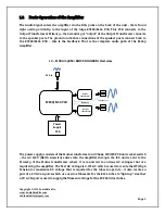
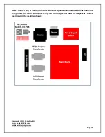
The Audio Signal enters the amplifier via the RCA jacks on the back of the unit - the left and
right audio go directly to the input of the large ECF80/EL34 PCB. This PCB connects to the
Output Transformers Primary – the Secondary or “output” of the Output Transformer connects
to the speaker posts. The ground and 8 ohm connections of the speaker posts connect back to
the ECF80/EL34 PCB – this is the feedback. That is the complete audio path of the EL34p
Amplifier.
Power
Supply
PCB
ECF80/EL34 PCB
Output
Transformer
Output
Transformer
RCA in
Speaker Post
Feedback
L4 – EL34 Amplifier BLOCK DIAGRAM Overview
The power supply consists of the Mains transformer and Choke, IEC/IEC PCB and rocker switch
– the AC 120V (North America) enters into the amplifier through the IEC and is sent to the
Primary of the Mains transformer where it is converted to various AC voltages that are
required by the amplifier. The first AC voltage is 0-275 AC which is used to create the HT (High
Tension) or maximum DC voltage that is required for the tubes to operate – it also creates a
pair of 6.3V AC 6A pairs which are used as filaments for the EL34 tubes to “light up”. Another
6.3V AC 1A pair is used to supply the filament voltage for the ECF80 driver tubes.


