Copyright © 2019 AudioNote Kits
www.AudioNoteKits.com
[email protected]
Page 44
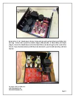
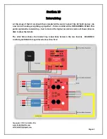
10.1 Power Supply PCB Interwiring
Note: In the following steps, make sure to measure the wire length before cutting and tinning.
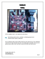
Looking at the slide on the previous page:
Connect the Blue and Yellow wires from the Mains Secondary to the Power Supply PCB as
shown– this is the 275 AC which creates the HT DC voltages. The orientation does not matter
– either the Blue or Yellow wire can go to either connection.
Connect the Choke Black wires to the Power Supply L1/AFC. The orientation does not matter
– either Black Choke wire can go to either connection.
Connect the Yellow (or, if supplied, Black) wires from the Power Supply B+ to the Yellow lugs
on the Output Transformers.
Connect one end of a Red wire to the Power Supply B+. This will go (in the next section) to
the ECF80/EL34 PCB B+. BE SURE TO MAKE THIS MORE THAN LONG ENOUGH!
Connect one end of a Green wire to the Power Supply GND. This will go (in the next section)
to the ECF80/EL34 GND. BE SURE TO MAKE THIS MORE THAN LONG ENOUGH!
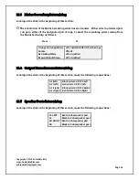
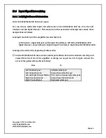
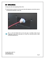
10.2 ECF80/EL34 PCB Interwiring
10.2.1 Wire Routing
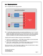
In order to keep wires away from the heat of the tubes and to improve the aesthetics of the
build, route the wires that connect to the ECF80/EL34 PCB under the board. You'll probably
have to figure out which wiring order works best for you. This is not an easy part of the build.
Take your time, be careful and patient. Take a break if you need to.
Looking at the slide on the previous page:
Solder the wires that will go to the ECF80/EL34 board closest to the transformers (speaker
post wires, output transformer wires, and PS PCB wires) inserting them from the top. Trim
and clean up as necessary.
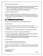
Next, turn over the board, support it with a book or other handy something, and solder the
Mains Secondary wires.


