Copyright © 2019 AudioNote Kits
www.AudioNoteKits.com
[email protected]
Page 34
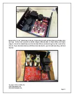
tool that does this neatly: try Googling "resistor bender".) If the leads (at right angles) are a
little too wide for the holes, try to bring each 'in' a bit with a neat additional bend. When you
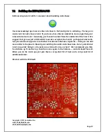
are done you may want to compare it with our high resolution photo of a populated board on
your disk.
Another point to remember, it’s a good idea to keep the resistors at least 1-2mm off the PCB.
This is for two reasons: first being heat related and the second is that in some places on the PCB
you will see large traces running underneath a resistor on the top of the board; for example,
R28, R11, R12 , R13 , R25 and R30. Also, consider installing the resistors with the color code
reading from left to right so that all resistors will be reading in the same direction. It makes it
easier for any future debugging or for recognizing resistors in correct positions. Once resistors
are installed we would recommend you check high resolution images to make sure all is well.
7.2.2 Capacitor Installation
Electrolytic Capacitors
The cap in middle of the board with no designation is C3 for the 100uf 450v cap. Position it
correctly!
Quantity
Designation
Description
2
C1-1,C1-2
10uf 160V
1
C3
100uf 450V
1
C9
33uf 350V
2
C15-1,C15-2
220uf 100V
2
C16-1,C16-2
220uf 100V
1
C17
22uf 100V
1
C20
10uf 100V
Other capacitors
Quantity
Designation
Description
2
C6-1,C6-2,C8-1, C8-2
100pf
2
C7-1,C7-2
220pf
2
C14-1,C14-2
.1uf 50V
These caps do not have any orientation and can be positioned on the board in either
orientation. They also have some unusual markings, but I don't think you'll have too much
difficulty figuring them out!


