

DCU20
User Manual rev. 19
Page 15/29
4.5 Connecting the INHIBIT input
An opto-isolated digital input is provided. A digital signal between 5VDC and 30VDC must be applied
to this input to enable the INHIBIT function. By default when the signal is 0V (or the INHIBIT input is
not connected) the unit will switch the load to the battery as soon as the input voltage is no more
present. Applying a signal to this input inhibits the backup function and the load can be switched OFF
as soon at the input fails with no battery backup. The polarity of this input can be changed as
explained in §5.2.15.
4.6 Dry contacts
2 relays
’ dry contacts are provided on the DCU20. Connect the 2 relays dry contact using 60/75 Class
I copper 0.15…0.5mm
2
wires stripped 7...8mm. The connector is provided with spring terminals.
Note
: the 2 relays contacts have one pole in common.
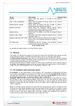
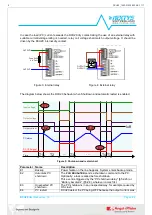
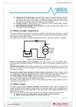
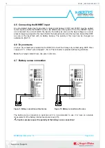
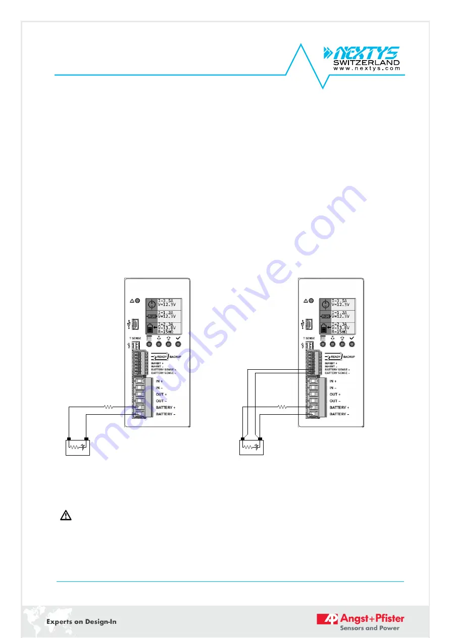
4.7 Battery sense connection
Ri
+
-
Rcables
Battery
Figure 9: Battery connection without sense
Ri
+
-
Rcables
Battery
Figure 10: Battery connection with sense
The battery sense connection is optional and it is recommended to use it to have an accurate
measurement of the battery internal resistance (see §3.5).
Caution: please respect the polarity of the battery sense connection!
15
DCU20_1680-21539-0006-E-1117