EVAL-AD7177-2SDZ User Guide
UG-849
Rev. 0 | Page 9 of 14
SOFTWARE OPERATION
OVERVIEW OF THE MAIN WINDOW
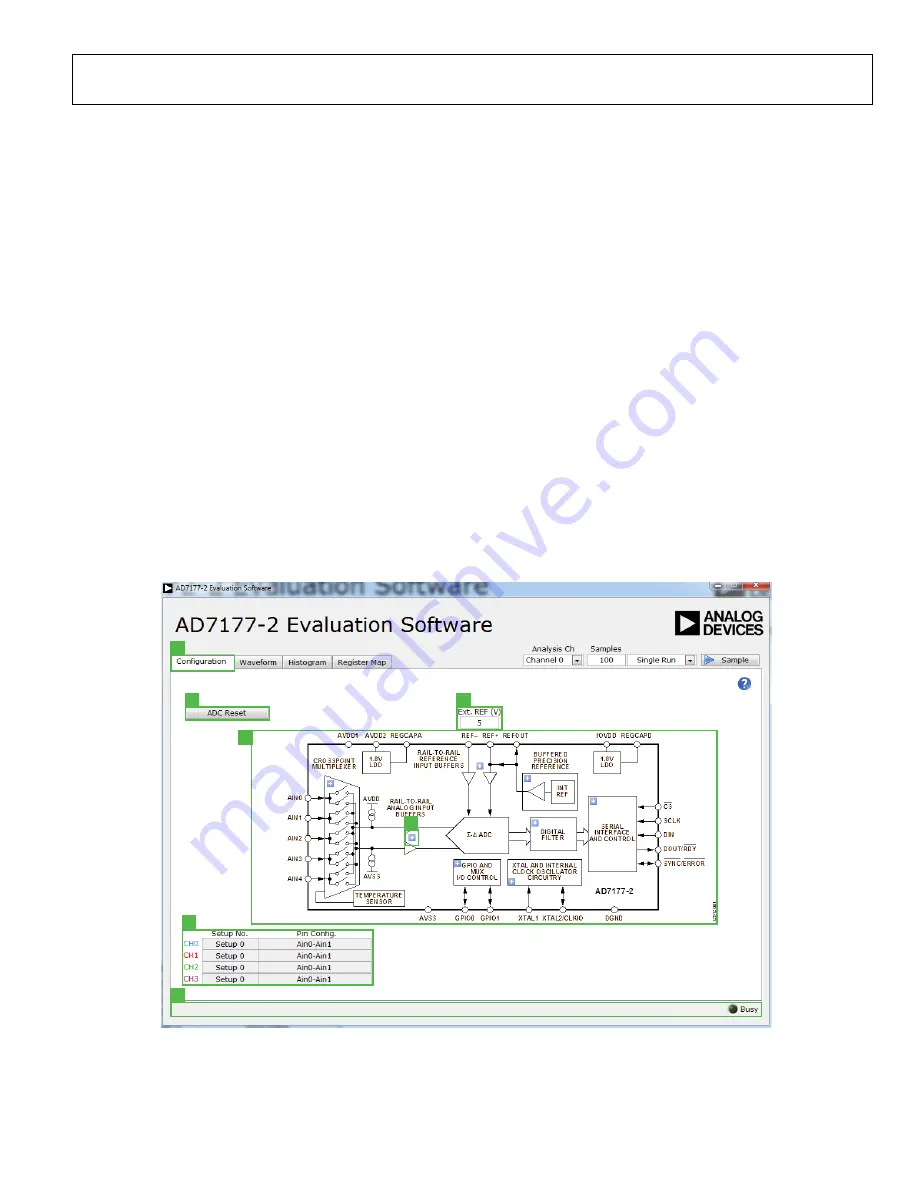
The main window of the software displays the significant
control buttons and analysis indicators of the
AD7177-2
evaluation board software (see Figure 7). This window is
divided into four tabs:
Configuration
,
Waveform
,
Histogram
,
and
Register Map
.
CONFIGURATION TAB (1)
See Figure 7 for the
Configuration
tab.
ADC Reset (2)
Click the
ADC Reset
button to perform a software reset of
the
AD7177-2
. There is no hardware reset pin. Perform a hard
reset by removing power to the board. The software reset has
the same effect as a hard reset
External Reference (3)
The
Ext. REF (V)
box sets the external reference voltage used
for calculating the results on the
Waveform
and
Histogram
tabs. The evaluation board has an external 5 V
ADR445
reference that can be disconnected by removing R32. You can
change the external reference voltage value within this box to
ensure the correct calculation of results on the
Waveform
and
Histogram
tabs.
Functional Block Diagram (4)
The functional block diagram of the ADC shows each of the
separate functional blocks within the ADC. Click one of the
configuration buttons in this graph to open the configuration
pop-up window for that block. Not all blocks have a configura-
tion button.
Configuration Pop-Up Button (5)
The configuration pop-up button opens a window that allows
for configuration of the relevant functional block.
Channel Configuration Overview (6)
The channel configuration overview section shows the channel
configuration including setup and analog inputs. This allows for
a quick check of how the ADC is setup.
Status Bar (7)
The status bar displays status updates such as
Analysis
Completed
and
Reset Completed
during software use as well
as the software version and
Busy
indicator.
1
2
3
4
5
6
7
13
282
-00
7
Figure 7.
Configuration
Tab of the
AD7177-2
Evaluation Software


