Preliminary Technical
Data
Rev. PrA | Page 40 of 82
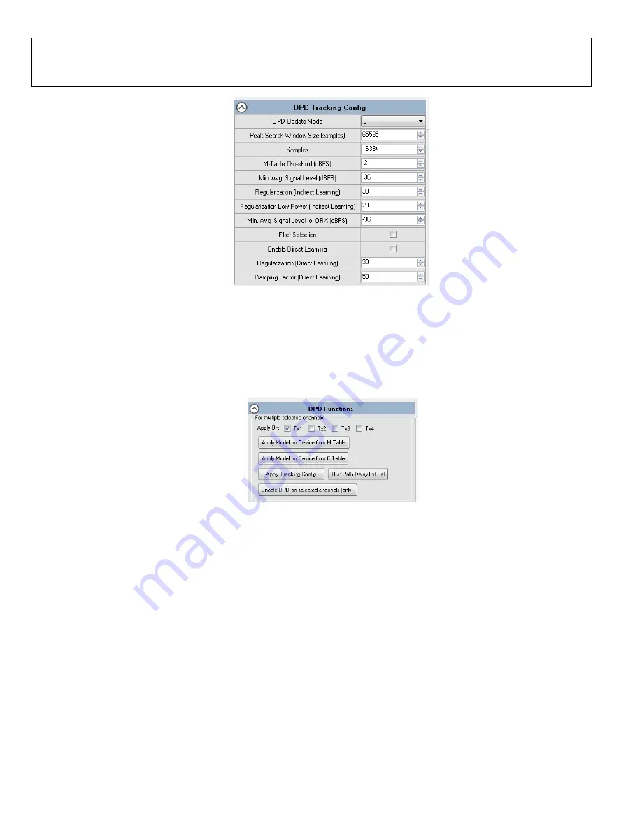
Figure 47. Configure DPD Tracking Config
3.
Select desired Tx channel to apply settings.
4.
Apply DPD tracking configuration by clicking on ‘Apply Tracking Config’, as shown in Figure 48.
5.
Run Path Delay initial calibration using ‘Run Path Delay Init Cal’ button.
6.
Apply DPD model on the M or C tables using ‘Apply Model on Device from M Table’ and ‘Apply Model on Device from C Table’
buttons. See Figure 48.
7.
Click ‘Enable DPD on selected channels (only)’ to enable DPD Tracking.
Figure 48. Apply DPD Settings
8.
DPD status and statistics can be revealed by using ‘Get Status and Statistics’ for the respective Tx channel. See Figure 49.
9.
‘Reset DPD’ button in Figure 49 appies a full reset to DPD.
10.
From the functional window in Figure 49, user can fetch the model on the device with ‘Fetch Model on Device from M Table’
and ‘Fetch Model on Device from C Table’.
11.
The DPD tracking configuration that the chip is currently using can be fetched with ‘Get Tracking Config’.


