


Preliminary Technical
Data
Rev. PrA | Page 26 of 82
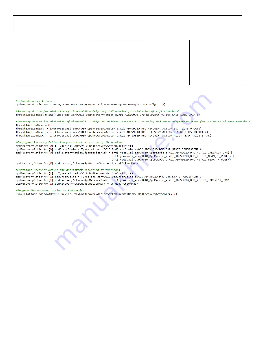
RECOVERY
ACTION
Do Nothing
Skip DPD LUT Updates
Do Nothing
Skip DPD LUT Updates
AND Reset DPD
coefficients to unity
gain(Actuator output =
Actuator input)
FAULT
CONDITION
-
Indirect EVM OR Mean Tu
Power OR Peak Tu Power
-
Indirect EVM Only
Figure 28. Recovery Action Example
The following is an example code snippet to setup recovery actions shown in the matrix above:
DPD ACTUATOR GAIN MONITORING FOR ROBUSTNESS
Principle of Operation
The DPD gain monitoring mechanism uses power meters at the input and output of the DPD actuator to determine when to
switch between DPD models if the actuator gain violates a programmable threshold. The gain monitoring mechanism can be used
to monitor gain over range as well as gain under range. Gain over range can occur when DPD is trying to expand gain to
compensate for gain compression. A gain under range condition can occur due to bad coefficients or gain compression.
Gain can be monitored either sample by sample or averaged over a number of samples. The maximum number of samples that
can be averaged is 128k samples (~266 µs worth of samples at a 491.52 MSPS rate). The average gain over several thousands of
samples should not typically exceed 1 dB. The gain monitoring mechanism can be setup to switch to a unity gain or any other
model if the gain/attenuation across the actuator is in the range of several dBs. Figure 29 represents a high level overview of the
DPD actuator hardware in the signal chain.
Table 2 explains the DPD models implemented in the transceiver. The user has an option to switch to either one of these 4 DPD
models in case the actuator output experiences high gain or high attenuation as explained in the previous section