


User Manual - VPX-1701
16
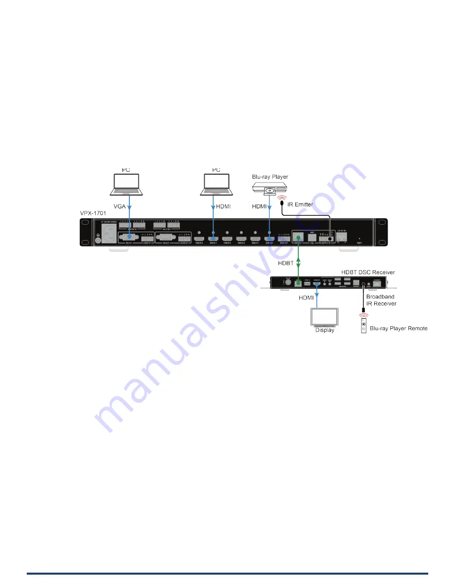
IR Operation
The IR pass-through function allows remote control of the source from the display location or the display from the source location.
Control the Source
To control the source from the display location:
1.
Connect an IR emitter to IR port of the VPX-1701;
2.
Connect a broadband IR receiver to the IR IN port of an HDBT receiver.
When the connections are complete, the source can be controlled at the display location through a source remote.


