

QUICK START GUIDE
Enova DGX 100 Series Digital Media Switchers
Overview
Enova DGX 100 Series Digital Media Switchers are available in various configurations in
increments of four up to 8x8, 16x16, 32x32, and 64x64. Therefore, the illustrations in
this guide may differ from the model(s) purchased. Each enclosure contains an
integrated NetLinx Central Control Processor. For complete documentation (including
system and board specifications and supported resolutions), see the
Hardware
Reference Manual – Enova DGX 100 Series Digital Media Switchers
at www.amx.com.
Installation
Rack Mounting
CAUTION:
To prevent overheating, avoid placing high heat-producing equipment directly
above/below enclosure. The system requires a minimum of 1 empty rack unit above and
below (3 empty rack units are recommended). Verify that the openings on the sides and
top of the enclosure are not blocked and do not have restricted airflow.
To rack mount a DGX 800/1600/3200 enclosure (3200* requires 2 people min.):
1.
Position enclosure in rack and secure it with rack mounting screws.
2.
Provided/recommended for DXLink Fiber Boards – Install cable management bars:
Fasten bar with two screws on one end of board and one screw at the other
(FIG. 2) (the long part of the bar is to right of holes); do not over tighten.
DGX 3200 only
– Remove number plate at rear top; replace when done.
* When fully loaded, the Enova DGX 3200 weighs approximately 73 lbs (33.1 kg).
To rack mount a DGX 6400 enclosure (requires 3 people minimum):
1.
While shipping box is still on the pallet, cut and remove outer straps.
2.
Remove cardboard tray from top of shipping box (note wheels on box).
3.
Lift box off pallet. The DGX 6400 weighs approximately 150 lbs (68.0 kg) fully
loaded.
Ensure all parties involved in lifting are prepared and follow local
requirements.
4.
Unlock 4 latches on sides of shipping box. Lift top of box straight up and set aside.
5.
Attach 2 handles provided for lifting; use 4 of 6 holes on side, in front or rear
position.
6.
Using bottom of shipping box, roll the enclosure into position. Lift onto temporary
shelf/support in rack. Align as closely as possible and then remove lifting handles.
7.
Lift into position and screw in rack ear screws.
8.
DXLink Fiber Boards only
– see Step 2 in the first set of instructions for installing
cable management bars.
Attaching Input and Output Cables
Generally, any input board in an Enova DGX Switcher can route signals to any type of
output board; signal format is automatically converted to match output board.
DXLink™ Twisted Pair I/O Boards require DXLink™ Twisted Pair TXs and RXs. DXLink™
Fiber I/O Boards require DXLink™ Fiber TXs and RXs. For details, see each product’s
Quick Start Guide
or
Hardware Reference Manual
.
For testing purposes (via Control Panel or System Configuration interface), attach first
two source and destination devices (and any required TXs and/or RXs).
Enova DGX ASB, AIE, HDMI, DVI, and DXLink Boards
Audio Switching Boards (ASB)
– Support audio breakaway and downmixing for
embedded or inserted audio with Digital Signal Processing capabilities on every output.
Audio Insert/Extract (AIE) Board
– This board is documented separately. Before
wiring, AIE boards must be uninstalled, have their DIP switches set, and be reinstalled.
For directions, see the
Quick Start Guide - Enova DGX Audio Insert/Extract Board
.
HDMI and HDMI 4K Boards (HDCP 1.4)
– Inputs and outputs incorporate HDMI®
technology.
HDMI connectors route high-resolution HDMI or DVI signals with or without HDCP.
For single-link DVI signals, use a cable adapter. 4K HDMI Boards require Category 2
high-speed cable for use with 4K content.
DVI Boards (HDCP 1.4)
– Inputs and outputs are HDMI compatible. If required,
DVI-specific EDID is available via the EDID Library at www.amx.com.
NOTE:
If an HDCP signal is switched from an HDMI or DVI Output Board to a destination
which does not support HDCP, display of a dark red image indicates authentication
failure. For HDCP signals switched via DXLink hardware, an orange image indicates
authentication failure.
DXLink Twisted Pair Boards (HDCP 1.4)
– Inputs and outputs incorporate HDMI
technology. Use with DXLink Twisted Pair TX and RX units, which automatically adjust
the scaling and image and almost always result in a quality image on the monitor. When
used with DXLink Twisted Pair equipment, DXLink Twisted Pair 4K equipment adjusts to
only provide support that matches the capabilities of the equipment. See the
Hardware
Reference Manual – DXLink Twisted Pair 4K TXs/RXs
for compatibility.
DXLink Fiber Boards (HDCP 1.4)
– Inputs and outputs incorporate HDMI technology.
DXLink Fiber boards and units are available for duplex and simplex functionality (with
multimode and single mode options for each) for various system requirements. Use with
DXLink Fiber TX and RX units, which automatically adjust scaling and image, resulting in
a quality image on the monitor. If the setup has special requirements or adjustment is
needed, see the manual.
Recommended – Fasten cable management bars with 2 screws on one end of board and
1 screw at other (long part of bar is to right of holes); do not over tighten (FIG. 2 left).
WARNING:
DXLink Fiber units use laser transceivers, which are Class 1 Eye Safe per IEC
60825-1/CDRH requirements. Class 1 category indicates that invisible laser used is safe;
we recommend avoiding direct eye exposure when using any optical fiber products.
CAUTION:
DXLink Fiber Boards – we recommend using the provided cable management
bars or another type of cable management system to avoid damage to fiber cables.
IMPORTANT:
If not using auto-setup, DIP switches must be set on DXLink Transmitter
and Receiver Modules before units are cabled to the switcher via their boards. For
information on DXLink Transmitters and Receivers, see the unit’s “Quick Start Guide.”
Audio EDID Settings
HDMI, DVI, DXLink Twisted Pair Boards ship with a basic audio EDID configuration.
DXLink Fiber Boards obtain EDIDs upon connection to their Transmitters. To optimize
audio for your system, you may need to change the EDID settings using the System
Configuration interface. Custom EDID files are available in the AMX_EDID_Library at
www.amx.com. For information, see the manual.
Applying Power and Startup
DGX 800/1600/3200 systems each have two power supplies; DGX 6400 has four.
NOTE:
We recommend using a surge protector and/or an AC line conditioner.
IMPORTANT:
If system is used to power DXLink Twisted Pair TXs/RXs, use the “Enova
DGX Configuration Tool” at www.amx.com/enova to calculate power draw.
Enova DGX 6400 only
- If two or more power supplies are not receiving power, CPU and
control panel will continue to operate. However, I/O boards will become inoperable and
system will not send/receive signals until >3 power supplies resume functional status.
For proper redundant operations, all power supplies must be powered at all times.
• Enova DGX 800/1600
– Cable power via power strip to outlet connected to a
single 20 A circuit.
• Enova DGX 3200 – Cable primary power feed to outlet connected to one 20 A
circuit breaker. Cable redundant power feed to outlet connected to a second 20 A
circuit breaker.
• Enova DGX 6400 – To provide adequate power for an N+1 redundant application,
connect each of the four power supplies to its own circuit.
To apply power:
1.
Plug power cords into
all power receptacles
(Enova DGX 6400 only – use provided
AC power filtering clamp-on Ferrites on cords as close to the power supplies as
possible).
2.
Plug the other ends of the power cords into power sources.
3.
Turn on the power strip and wait until the system status indicator flashes green.
4.
Check the Indicator LEDs on front and rear of the enclosure; see table below.
5.
For Enova DGX 800/1600/3200 systems with ASB Boards – Attach HSSI cable
from SMA port on ASB Input Board to SMA port on ASB Output Board.
6.
For systems with boards that require modules – Apply power to the modules.
7.
Apply power to the source and destination devices.
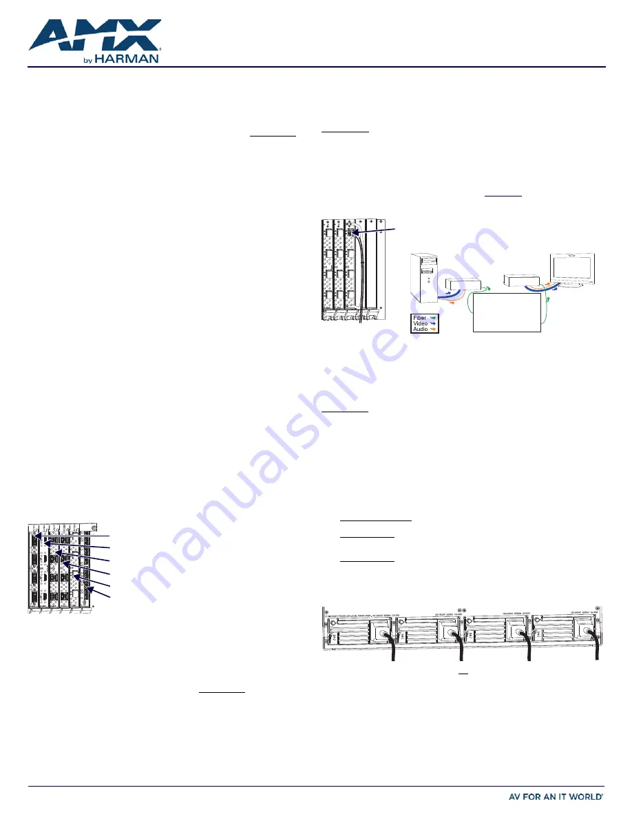
FIG. 1
HDMI, DVI, DXLINK, AND ASB BOARDS SHOWN
NOTE:
System setup for DXLink
Twisted Pair Boards is similar to
FIG. 2 right, except with DXLink
Twisted Pair TXs and RXs
installed between the DXLink
Boards and the source and
destination devices.
DVI Board
HDMI / HDMI 4K Board
Audio Switching Board
DXLink Fiber Board
DXLink TP 4K Board
DXLink TP Board
FIG. 2
DXLINK FIBER CABLE ATTACHED TO INPUT; SYSTEM SETUP WITH DXLINK FIBER
FIG. 3
POWER CORDS MUST BE PLUGGED INTO ALL POWER RECEPTACLES (DGX 6400 SHOWN)
System Setup
DXLink Fiber TX DXLink Fiber RX
NOTE:
Avoid network loops (created
when enclosure and 1 or more TX/RX
units in a system are connected to a
common LAN).
DXLink Fiber connector
(make sure it seats firmly;
normally a click is heard)
Enova DGX Switcher
DXLink Fiber Input
DXLink Fiber Output


