background image

MXR-1001

11

MXR-1001 - Installation & Hardware Reference Manual

Configuration and Programming

MXR-1001 touch panels are equipped with a 

Settings

 menu that provides the ability to configure various features on the panels. To 

access the 

Settings

 menu, press and hold the Sleep button, and select 

Settings 

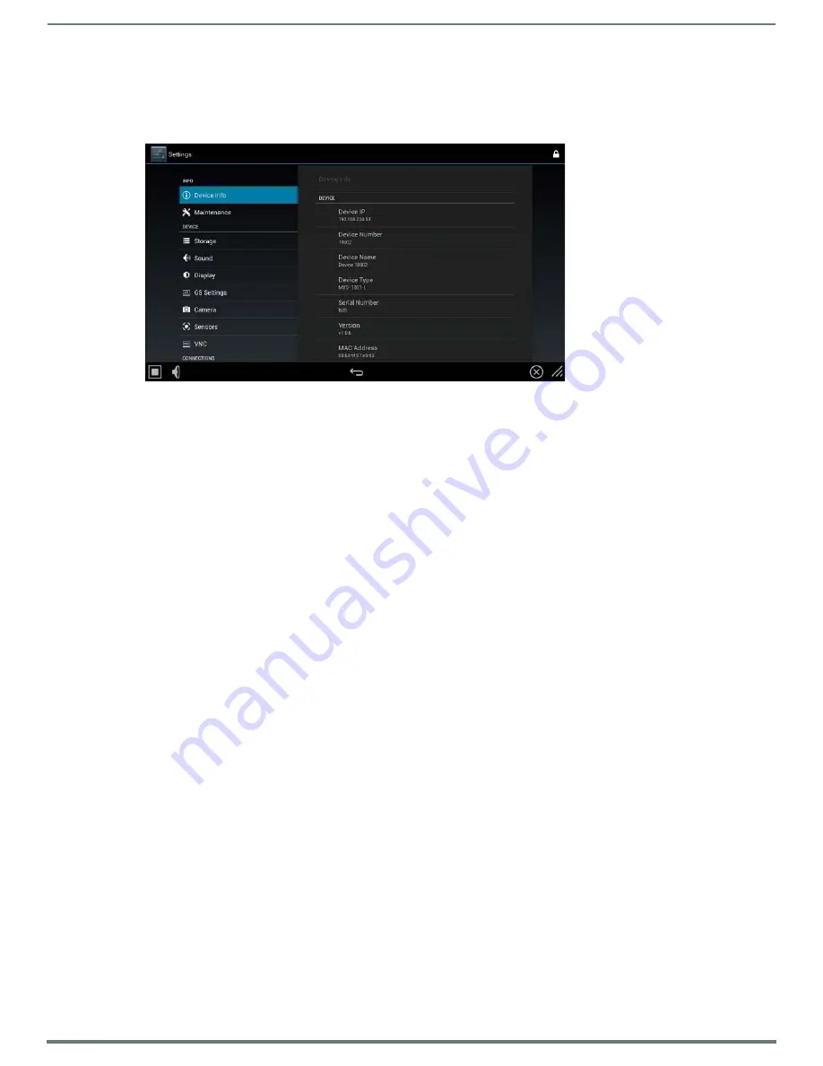
(FIG. 3). This opens the main Settings menu 

(FIG. 6): 

NOTE: 

The MXR-1001 Settings menu is similar to the Settings menu on other X Series G5 touch panels. The main difference is the 

addition of the "Panel Raise Sound Select" and "Panel Lower Sound Select" options in the Sound page, and the removal of G5 

features that are not available on the MXR-1001. Refer to the Modero X® Series G5 Touch Panels Configuration & Programming 

Manual for details.

MXR-1001 Send Commands

There are two new G5 Send Commands that are specific to the MXR-1001: 



"'^MCC-<MOTOR|LOCK|AUTHENTICATION|LED>’"

 -

 Motor Controller Control/Configure

. This command uses multiple 

sub-commands to configure Motor, Lock, Authentication and LED settings.



"'?POS-<id>'"

 - 

Panel Position Query

. Requests the current position of the panel. A new custom event (custom event type 

1602) 

reports the status of the Motor Controller, including its state and whether or not the lock feature is on. 

This event is sent either in reply to the “?POS” query, or unsolicited to report a status change. It is also sent when the panel 

first comes online to report initial status.

Refer to the 

Modero X® Series G5 Touch Panels Configuration & Programming Manual 

for details on using these commands, as well 

as all standard G5 Send Commands.

NOTE: 

Note: Programming the Modero X Series G5 touch panels require the use of the latest versions of NetLinx Studio and 

TPDesign5, both are available to download at www.amx.com.

Cleaning the Touch Overlay and Case

The MXR-1001comes with the MXA-CLK Modero X Series Cleaning Kit (FG5968-16), which may be used to clean fingerprints and 

dirt from the device. This kit comes with cleaning cloths and a bottle of cleaning fluid specifically for use with the device.



When cleaning the device, 

do not directly spray the device with cleaning fluid

. Instead, spray the cloth and then apply the 

cloth to the touch screen. 



Do 

NOT

 use abrasives of any type to clean the device, as abrasives may permanently damage or remove the device’s finish.

Additional Documentation

Refer to the 

Modero X Series G5 Touch Panels Configuration and Programming Manual

 for details on configuring and programming 

G5 touch panels, including:



Information on Modero X Series G5 Programming, including Transitioning from G4 to G5



Detailed descriptions of each page and page option available in the G5 Settings Menu



Firmware upgrades via the G5 Settings Menu (Reset and Update page)



Using Content Sharing



Using Gestures



MXA-MP and MXA-MPL Programming



Detailed descriptions of all G5-supported Send Commands and SSH Commands

NOTE: 

Refer to the Modero G5 Configuration and Programming - X Series G5 Touch Panels Instruction Manual for details.

NOTE: 

Touch Panel files for G5 Touch Panels are created via TPDesign5 software (available to download from www.amx.com). Refer to 

the TPDesign5 online help and Instruction Manual for details.

FIG. 6  

Main Settings menu

Summary of Contents for MXR-1001-BL

Page 1: ...TION HARDWARE REFERENCE MANUAL MODERO X SERIES G5 RETRACTABLE TOUCH PANELS MXR 1001 BL 10 1 MODERO X SERIES G5 RETRACTABLE TOUCH PANEL BLACK MXR 1001 SL 10 1 MODERO X SERIES G5 RETRACTABLE TOUCH PANEL...

Page 2: ...ble specified by the manufacturer or sold with the apparatus When a cart is used use caution when moving the cart apparatus combination to avoid injury from tip over 13 UNPLUG this apparatus during li...

Page 3: ...COMPLIANCE INFORMATION The term IC before the radio certification number only signifies that Industry Canada technical specifications were met Le terme IC avant le num ro de certification radio signi...

Page 4: ...r certifications asp WEEE NOTICE CHINA COMPLIANCE INFORMATION This appliance is labeled in accordance with European Directive 2012 19 EU concerning waste of electrical and electronic equipment WEEE Th...

Page 5: ...1 Unbox the MXR 1001 and Remove Shipping Screws 12 2 Select a Suitable Location 12 Mounting Surface Requirements 12 Above Surface Dimensions 13 Below Surface Dimensions 13 Hole Cutout Dimensions for t...

Page 6: ...MENSIONS HWD 15 325 x 11 010 x 6 753 389 25mm x 279 65mm x 171 53mm CUTOUT DIMENSIONS 10 701 x 1 984 271 81mm x 50 39 mm WEIGHT 18 85 lbs 8 55 Kg POWER CONSUMPTION Full On 15 6W in motion Full On no m...

Page 7: ...05 kHz 24 kHz 32 kHz 44 1 kHz 48 kHz AAC LC 8 kHz 96 kHz G 711 with Law VoIP encode decode at 8 kHz Suggested max packet size for G 711 Voice 20ms File Formats WAV MP3 as part of touch panel file onl...

Page 8: ...inguishing feature of the MXR 1001 is the ability to raise and retract the touch panel Therefore there are electrical and firmware features specific to the MXR 1001 that provide control of the motoriz...

Page 9: ...ed to a Master for example during installation as long as the MXR 1001 is powered Audio Alert The Audio Alert feature allows the MXR 1001 to play a sound when the panel is raised and or a separate sou...

Page 10: ...using these commands as well as all standard G5 Send Commands NOTE Note Programming the Modero X Series G5 touch panels require the use of the latest versions of NetLinx Studio and TPDesign5 both are...

Page 11: ...nd remove packing materials Note that the MXR 1001 ships with two Shipping Screws installed on the bottom surface of the Motor FIG 7 2 Remove the Shipping Screws before installing the MXR 1001 2 Selec...

Page 12: ...talled MXR 1001 to indicate the area required below the mounting surface for the chassis and Mounting Clamps FIG 8 Above Surface Dimensions of MXR 1001 FIG 9 MXR 1001 Top view indicating area required...

Page 13: ...e dimensions of the actual hole cut out in the mounting surface resulting from using the Router Guide and required accessories FIG 10 Dimensions of the MXR 1001 side view below the mounting surface FI...

Page 14: ...top surface of the mounting surface is not damaged beyond the width of the trim bezel as the cutout is made NOTE The process of making the cutout will create substantial dust prepare the environment a...

Page 15: ...located on the front of the Bezel 5 Route the MXR cable from the Bezel through the slot on the front center of the Bezel and run it through the cutout hole 6 Lower the Bezel through the cutout hole a...

Page 16: ...Clamps slide into the two matching ratcheted Clamp Slots on each side of the Motor chassis To install the Mounting Clamps on the sides of the Motor chassis a Insert each Mounting Clamp into a ratchete...

Page 17: ...o a Gigabit Ethernet Switch For information on pinouts signals and LED blink patterns for this connector refer to the MXR 1001 Hardware Installation Guide NOTE Clip the included snap on cable Ferrite...

Page 18: ...st long enough to wake the panel and then turned off Depending on the switch the cycle time could be as little as three or four seconds A test should be conducted to determine the minimum dwell time t...

Page 19: ...aise or lower the panel To manually lower the touch panel turn the lead screw clockwise until it is fully lowered To manually raise the touch panel turn the lead screw counter clockwise until it is fu...

Page 20: ...Most firewalls will not allow ping requests to pass through for security reasons When connecting to a NetLinx Master controller via TCP IP the program will first try to ping the controller before att...

Page 21: ...s not assume responsibility for errors or omissions AMX also reserves the right to alter specifications without prior notice at any time The AMX Warranty and Return Policy and related documents can be...

Reviews: