background image

Installing Wall-Mount (MXD) Panels

29

Modero S Series Touch Panels - Installation & Hardware Reference Manual

Removing the MSD-1001-L from the Backbox

The clips on the bottom edge of the Backbox lock down the MSD-1001-L and must be unlatched in order to remove the touch panel 

from the Backbox. To do this, you ll need a thin probe such as an straightened paper clip:
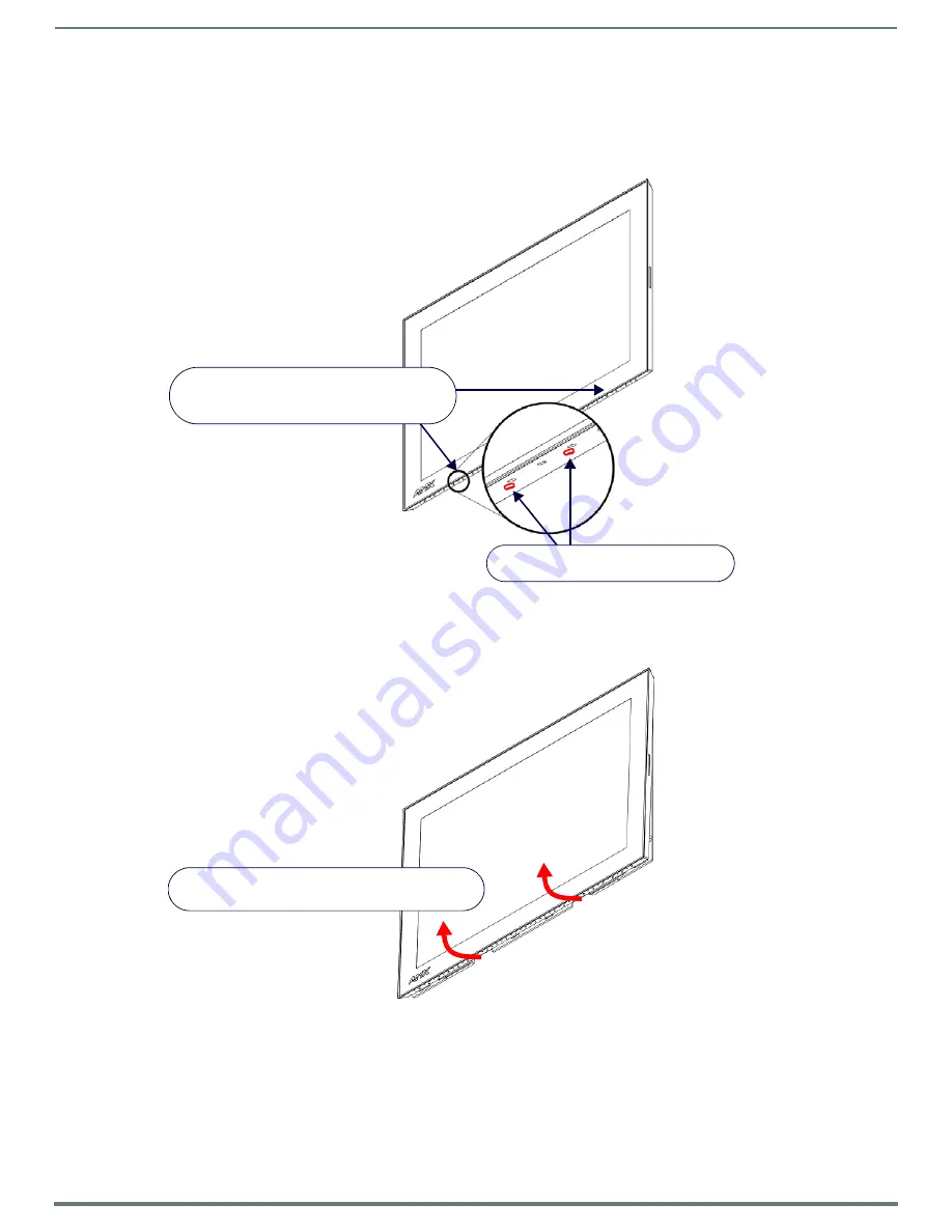
1.

With a straightened paper-clip, carefully press straight into the access holes indicated in FIG. 26, to disconnect the two bottom 

latches.


2.

Grasp the bottom of the panel and gently pull outward until the bottom edge of the panel is free of the Backbox. Use your 

other hand to stabilize the front of the touch panel. Always pull on the panel’s plastic bezel - NEVER pull on the glass edge 

(FIG. 27): 

3.

With the bottom edge of the panel free, carefully lift up and out to release the tabs on the top edge of the panel.

FIG. 26  

MSD-1001-L/BACKBOX ASSEMBLY

FIG. 27  

MSD-1001-L/BACKBOX ASSEMBLY (RELEASING THE BOTTOM EDGE OF THE PANEL)

Gently press up through these holes with a thin 

probe such as a straightened paper clip to 

release the panel from the tabs in the Backbox

Insert probe through either hole to push 

the tab in and away from the panel

Lift the bottom edge of the panel by the plastic bezel 

and gently rotate up and away from the Backbox

Note: To avoid damaging the 

panel, always pull on the plastic 

bezel - do not pull on the glass.

Note: Hold the panel to prevent it from 

falling once the bottom edge is free

Summary of Contents for MST-1001

Page 1: ...ETOP TOUCH PANEL MSD 1001 L 10 1 MODERO S SERIES LANDSCAPE WALL MOUNT TOUCH PANEL MST 701 7 MODERO S SERIES TABLETOP TOUCH PANEL MSD 701 L 7 MODERO S SERIES LANDSCAPE WALL MOUNT TOUCH PANEL MST 431 4...

Page 2: ...es and the point where they exit from the apparatus 11 ONLY USE attachments accessories specified by the manufacturer 12 USE ONLY with a cart stand tripod bracket or table specified by the manufacture...

Page 3: ...een the equipment and receiver Connect the equipment into an outlet on a circuit different from that to which the receiver is connected Consult the dealer or an experienced radio TV technician for hel...

Page 4: ...leaning the Touch Overlay and Case 9 MST D 1001 10 1 S Series Touch Panels 10 MST 1001 Tabletop 10 MST 1001 Specifications 10 MSD 1001 L Wall Mount Landscape 12 MSD 1001 L Specifications 12 Touch Pane...

Page 5: ...30 MXD 1001 L Dimensions 30 MXD 701 L Dimensions 31 MXD 431 L Dimensions 32 Upgrading Firmware 33 Overview 33 Downloading Firmware Updates From www amx com 33 Upgrading Firmware via USB Flash Drive 33...

Page 6: ...mode as well as to power down and power up the panel and to access the Setup pages The Sleep button is located on the top left edge of the frame when facing the panel see FIG 2 The Sleep Button s Func...

Page 7: ...econds of these dots appearing on the screen Using the Settings Pages When opened the Settings menu appears in the center of the panel display Note that many of the pages may be longer than they initi...

Page 8: ...the last one uploaded to date 5 On the rightmost red button select the number of seconds a selected image will be displayed in Picture View This may be selected between 5 10 15 30 and 60 seconds 6 The...

Page 9: ...Exit the Calibrate page by pressing the Back button to return to the Protected Setup page NOTE If the calibration was improperly set and you cannot return to the Calibrate page through the panel s fi...

Page 10: ...upplies not included PS POE AF TC PoE Injector 802 3AF Compliant FG423 83 NXA ENET8 2POE Gigabit PoE Ethernet Switch FG2178 63 CERTIFICATIONS FCC Part 15 Class B CE EN 55022 CE EN 55024 CE EN 60950 1...

Page 11: ...ng force behind the advanced graphics and image processing capability on a variety of AMX Touch Panels and other devices see TPD4 Operations Guide for more information EMBEDDED APPLICATIONS Remote Man...

Page 12: ...tor 802 3AF Compliant FG423 83 NXA ENET8 2POE Gigabit PoE Ethernet Switch FG2178 63 CERTIFICATIONS FCC Part 15 Class B CE EN 55022 CE EN 55024 CE EN 60950 1 IEC 60950 1 C Tick CISPR 22 Class B IC CISP...

Page 13: ...nd the advanced graphics and image processing capability on a variety of AMX Touch Panels and other devices see TPD4 Operations Guide for more information EMBEDDED APPLICATIONS Remote Management VNC S...

Page 14: ...tor 802 3AF Compliant FG423 83 NXA ENET8 2POE Gigabit PoE Ethernet Switch FG2178 63 CERTIFICATIONS FCC Part 15 Class B CE EN 55022 CE EN 55024 CE EN 60950 1 IEC 60950 1 C Tick CISPR 22 Class B IC CISP...

Page 15: ...iving force behind the advanced graphics and image processing capability on a variety of AMX Touch Panels and other devices see TPD4 Operations Guide for more information EMBEDDED APPLICATIONS Remote...

Page 16: ...equires use of one of the following AMX PoE power supplies not included PS POE AF TC PoE Injector 802 3AF Compliant FG423 83 NXA ENET8 2POE Gigabit PoE Ethernet Switch FG2178 63 CERTIFICATIONS FCC Par...

Page 17: ...rocessing capability on a variety of AMX Touch Panels and other devices see TPD4 Operations Guide for more information EMBEDDED APPLICATIONS Remote Management VNC Server G4 Web Control Panel to Panel...

Page 18: ...802 3AF Compliant FG423 83 NXA ENET8 2POE Gigabit PoE Ethernet Switch FG2178 63 CERTIFICATIONS FCC Part 15 Class B CE EN 55022 CE EN 55024 CE EN 60950 1 IEC 60950 1 C Tick CISPR 22 Class B IC CISPR 2...

Page 19: ...erations Guide for more information EMBEDDED APPLICATIONS Remote Management VNC Server G4 Web Control AMX Resource Management Suite Video Conferencing Panel to panel and video chat the MST 431 receive...

Page 20: ...due to PoE standard EXTERNAL POWER SUPPLY REQUIRED Optimal performance requires use of one of the following AMX PoE power supplies not included PS POE AF TC PoE Injector 802 3AF Compliant FG423 83 NX...

Page 21: ...devices see TPD4 Operations Guide for more information EMBEDDED APPLICATIONS Remote Management VNC Server G4 Web Control AMX Resource Management Suite Video Conferencing Panel to panel and video chat...

Page 22: ...ns USB peripherals mouse keyboard etc may be connected to the USB port on the rear of the device Updates to the device s firmware can also made via the USB port Note that FIG 12 shows a MST 1001 but t...

Page 23: ...st be taken into consideration to maintain the product within the specified operating temperature FIG 13 shows an AMX device installed in a wall with a filled volume such as with insulation or concret...

Page 24: ...kbox can be used to mount the touch panel into most standard wall materials The Backbox can also used to mount the panel into other mounting options FIG 15 shows the Backbox for the MSD 1001 L FIG 16...

Page 25: ...dimensions as the touch panel which allows you to troubleshoot possible conflicts with wall edges doors and other potential obstacles NOTE Prepare the area by removing any screws or nails from the dry...

Page 26: ...little wall material removed is always better than too much 2 Thread the incoming cables Ethernet and Micro USB from their terminal locations through the surface opening leaving enough slack in the wi...

Page 27: ...e sure that it is positioned correctly FIG 21 MSD 1001 L Backbox Locking tab and locking tab screws X4 FIG 22 MSD 701 L Backbox Locking tab and locking tab screws X2 FIG 23 MSD 431 L Backbox Locking t...

Page 28: ...s and the top hooks on the Backbox LOWER TABS Gently Snap Into Place 1 Swing the bottom edge of the touch panel into position until it rests against the lower outside edge of the Backbox NOTE If a gap...

Page 29: ...d to stabilize the front of the touch panel Always pull on the panel s plastic bezel NEVER pull on the glass edge FIG 27 3 With the bottom edge of the panel free carefully lift up and out to release t...

Page 30: ...tallation Dimensions MXD 1001 L Dimensions Detailed specifications drawings for the MSD 1001 L are available to download from www amx com FIG 28 MST 1001 L Notes Dimensions in parenthesis are in milli...

Page 31: ...nce Manual MXD 701 L Dimensions Detailed specifications drawings for the MSD 701 L are available to download from www amx com FIG 29 MSD 701 L Notes Dimensions in parenthesis are in millimeters Additi...

Page 32: ...nce Manual MXD 431 L Dimensions Detailed specifications drawings for the MSD 431 L are available to download from www amx com FIG 30 MSD 431 L Notes Dimensions in parenthesis are in millimeters Additi...

Page 33: ...ion Upgrading Firmware via USB Flash Drive Firmware and TPDesign4 files may be transferred to the panel made via USB flash drive Load the Firmware on a USB Flash Drive 1 Insert the USB flash drive in...

Page 34: ...Upgrading from Previous Firmware S Series panels provide the option to revert the device to the previous firmware run before an upgrade To upgrade the device from previously loaded firmware 1 From th...

Page 35: ...er to the device page for firmware updates Transferring the KIT File via NetLinx Studio 1 In Netlinx Studio right click in the Online Tree tab of the Workspace window and select Refresh System Online...

Page 36: ...at the Reboot Device option is selected It is necessary to reboot the panel after a firmware upgrade 3 Click Send to begin the file transfer 4 The progress of the transfer operation is indicated in th...

Page 37: ...h a connection failure instantly if it is not Without using the ping feature a connection may still be attempted but a failure will take longer to be recognized NOTE If you are trying to connect to a...

Page 38: ...t assume responsibility for errors or omissions AMX also reserves the right to alter specifications without prior notice at any time The AMX Warranty and Return Policy and related documents can be vie...

Reviews: