background image

Protected Settings Menu

20

Mio Modero R-4

Password Entry

The 

Password Confirmation

 page protects the device’s system settings, network information and 

calibration from casual changes. Use the Numeral Keypad pushbuttons (FIG. 1) to enter passwords. The 
unit allows both numeric and alphanumeric passwords, with different procedures for entering each type. 

The default password is 

1988

, which has to be entered in the text entry field upon opening the 

Password 

Confirmation

 page for the first time.

Entering a numeric password

1.

Select 

Protected Settings

 in the Setup Menu.

2.

Press any button on the Protected Settings Menu to invoke the 

Password Confirmation

 page.

3.

Enter your password from the keypad. 

4.

After entering a password, select 

Done

 to submit it.

Entering an alphanumeric password

1.

Select 

Protected Settings

 in the Setup Menu.

2.

Press any button on the Protected Settings Menu to invoke the 

Password Confirmation

 page.

3.

Using the numeric keypad, follow the guide on the page to enter letters and other characters. For 
instance, to enter the letters a, b, or c, press "2" and then use the arrow keys to select the particular 
letter in the 

Text Entry

 field. Enter numbers simply by choosing the number from the keypad. Other 

characters are available by pressing "1".

4.

When done, press the 

Enter

 button on the keypad to return to the main password confirmation page.
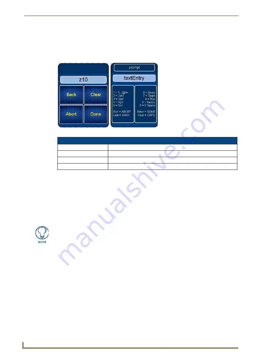
FIG. 13  

Password Confirmation Page

Password Confirmation

Back

Goes to the Alphanumeric Password Entry page

Clear

Clears the entry field

Abort

Shuts down the 

Password

 page without submitting a password

Done

Submits the password

Should you decide to leave the Password Confirmation page for any reason, press 
the Exit button (FIG. 1) to return to the last page displayed.

Summary of Contents for Mio Modero R-4

Page 1: ...Operation Reference Guide Mio Remote Controls Mio Modero R 4 ZigBee Pro Remote Control Last updated 8 22 2011 ...

Page 2: ... or after the RMA is cancelled will be refused AMX is not responsible for products returned without a valid RMA number AMX is not liable for any damages caused by its products or for the failure of its products to perform This includes any lost profits lost savings incidental damages or consequential damages AMX is not liable for any claim made by a third party or by an AMX Dealer for a third part...

Page 3: ...oject Information 10 Viewing Project Information 10 Remote Display Settings 11 Changing the remote timeout 12 Raising and lowering the LCD brightness 13 Raising and lowering the charge LED brightness 13 Setting the Home Hold Time 13 Changing the remote inactivity page flip 13 Checking remote display settings 14 Date Time Settings 15 Getting time and date from your NetLinx Master 15 Setting the tim...

Page 4: ...e touch screen area 24 System Settings 25 Checking connection status 25 Checking the master IP address 25 Checking the gateway IP address 26 Checking the Gateway EUI address 26 Checking the Extended PAN ID 26 Changing the Device Number 26 Site Survey 27 Joining a wireless network 27 ZigBee Diagnostics 28 Reboot Page 29 Rebooting the device 29 Test Pages 29 Programming the Mio R 4 31 Overview 31 Us...

Page 5: ... Text Effects Names 40 SEND_COMMANDs 41 Page Commands 41 PAGE 41 APG 41 CPG 41 DPG 42 PDR 42 PHE 42 PHP 42 PHT 43 PPA 43 PPF 43 PPG 43 PPK 44 PPM 44 PPN 44 PPT 45 PPX 45 PSE 45 PSP 45 PST 45 PPOF 46 PPOG 46 PPON 46 Button Commands with Embedded Codes 47 BMF 47 Button Commands 49 ANI 49 APF 49 BAT 50 BAU 50 BCB 50 BCF 51 BCT 51 BDO 52 ...

Page 6: ...5 BMP 56 BOR 56 BPP 56 BRD 57 BSF 57 BSM 57 BSP 57 BWW 58 CPF 58 DPF 58 ENA 58 FON 59 GDI 59 GIV 59 GLH 59 GLL 60 GRD 60 GRU 60 GSC 60 GSN 61 ICO 61 JSB 62 JSI 62 JST 63 SHO 63 TEC 63 TEF 64 TXT 64 UNI 64 Button Query Commands 65 BCB 66 BCF 66 BCT 67 BMP 67 BOP 68 ...

Page 7: ...74 ABEEP 74 ADBEEP 74 AKEYR 74 AKP 74 AKR 74 BEEP 75 BRIT 75 DBEEP 75 EKP 75 PKEYP 75 PKP 76 SETUP 76 SLEEP 76 TKP 76 TPAGEON 76 TPAGEOFF 76 Input Commands 77 CAL 77 VKB 77 WAKE 77 Remote Setup Commands 78 MUT 78 PWD 78 PWD 78 Listboxes 79 List Box Commands 79 LDN 79 Getting The Most From Your Mio Modero R 4 87 Overview 87 ...

Page 8: ...able of Contents Getting the Most From the Mio R 4 87 The ZigBee Network Calculator 89 The Mio Modero R 4 Return Button 90 Mio Remote Charging Base 91 Specifications 91 Charging The Mio Remote with Charging Base 92 ...

Page 9: ...e 2004 networks Selecting a source device sends a command to the master and runs predetermined events associated with that source Selecting a macro will run predefined events which might not be associated with sources listed then return the device to its previous mode FIG 1 The Mio R 4 front panel 1 2 3 4 5 6 7 8 9 10 11 12 13 14 15 16 17 18 Numeric Keypad 19 Touch Screen 20 1 Power 2 Guide 3 Exit...

Page 10: ...argeable Lithium Ion Transmission Frequencies ZigBee RF wireless network Transmission Range 100 feet 30 48m Refer to the The ZigBee Network Calculator section on page 89 for more information Memory 32 Mbytes of FLASH 64 Mbytes of SDRAM Top Components LED blue backlit buttons indicate device is awake LCD high resolution 240x320 76800 pixels with backlight and touch overlay Pushbuttons the power but...

Page 11: ...m Device Navigation The Mio R 4 allows you to scroll through pages using the up and down buttons beneath the touch screen Pressing the Back buttons moves the selection back by one page while holding the button down returns the device to the power up page Mio Modero R 4 FG148 04 Specifications Cont Optional Keypads Mio R4 KP ITALIAN FG148 141 Mio R4 KP FRENCH FG148 142 Mio R4 KP ARABIC FG148 143 Mi...

Page 12: ...n of this device The User Manual for the end device must contain the following statements in a prominent place in the manual Modifications not expressly approved by the manufacturer will void the user s authority to operate the equipment Patents This product is covered by the following patents AMX U S Patent No D 602 858 U S Patent No D 520 495 U S Patent No 7 786 623 This product employs or pract...

Page 13: ...rminal end of the Lithium Ion battery to the port shown in FIG 2 It may be necessary to use a thin blunt non conductive object to seat the battery connector fully within its port 4 Place the battery door back on the device and slide the door upwards to lock it in place FIG 2 Rechargeable Battery Port on The Mio Remote Lithium Ion Battery Rechargeable Battery Port Connection Rear view battery compa...

Page 14: ...ay a popup window reading Battery Low as an initial warning and then a popup window reading Battery Very Low to encourage the user to shut it down The device will then shut down to prevent a total discharge of the battery To recharge the battery insert the Mio R 4 into the Mio Remote Charging Base see Charging The Mio Remote with Charging Base section on page 92 ...

Page 15: ...ng Keypads To install a new keypad 1 Flip and turn the Mio R 4 so that the buttons are facing away from you and the device is upside down 2 Holding the Mio R 4 in both hands place your thumbs on the battery door and push up to slide the battery door free 3 Remove the battery 4 Unscrew the 6 screw points indicated in FIG 3 5 Turn the unit over so the buttons are facing you 6 Lift the top assembly a...

Page 16: ... Place the new keypad in the top assembly and verify the alignment with the guide posts on the PCB 9 Place the top assembly back down on the PCB and turn the unit over again exposing the 6 screw points 10 Tighten the 6 screw points 11 Install the battery replace the battery door and slide the door to lock it in place ...

Page 17: ...formation functions page 10 Remote Display Settings page 11 Date Time Settings page 15 Sound Settings page 17 Protected Settings page 19 Battery Settings page 18 Accessing the Setup Pages To enter Setup Menu Hold the Input and Back buttons see FIG 1 for 6 seconds Navigate the Setup pages using the onscreen menu selections and the up and down arrows FIG 4 Setup Page Menu ...

Page 18: ...gner ID The ID of the designer for the control pages File Revision The revision number for the control pages Dealer ID The ID of the dealer associated with the control pages Job Name A friendly name for the job associated with the control pages Sales Order The sales order number for the job Purchase Order The purchase order number for the job Build Number The current build version number for the d...

Page 19: ...me in seconds 0 6 in which the selected home page will be displayed Inactivity The amount of time in minutes 0 240 spent inactive in its charging cradle before the unit switches to its inactivity page Inactivity Page The selected page displayed when the inactivity timer expires Panel Type The type of unit connected to the ZigBee network This is always R4 Firmware Version The most current firmware ...

Page 20: ...ep timeouts press the Sleep on Display Timeout button When Sleep on Display Timeout is engaged the button is green FIG 7 and the Sleep Timeout settings will be greyed out Press the button again to re enable the Sleep on Display Timeout function Remote Display Settings Cont High Port The highest port number specified in the project pages High Address The highest address specified in the project pag...

Page 21: ...ou are out of the Setup Menu Make sure to adjust the Sleep Timeout period after disengaging the Sleep on Display Timeout function From the factory the default sleep timeout will be set for 15 minutes but engaging and then disengaging the Sleep on Display Timeout function will reset the period for 0 minutes will not sleep until the battery charge runs low because the previous setting will already h...

Page 22: ...4 Checking remote display settings 1 Select Remote Display Settings from the Setup Page 2 Use the device s arrow down to navigate to the fourth and fifth Display Settings pages 3 Select the Back button until you are out of the Setup Menu ...

Page 23: ...selected is displayed between the arrows 3 Select the Back button until you are out of the Setup Menu FIG 8 Date Time Settings Pages Date Time Settings Set Date Time Allows the user to get date and time information from the NetLinx master or to set changes made manually Time Format Selects between displayed standard and military time formats Date Format Selects displayed date format Year Selects t...

Page 24: ...nd Down arrows under Year Month and Day to increment each by 1 until correct 4 Use the Up and Down keys to return to the first Date Time Settings page 5 Select the Set button to save your settings 6 Select the Back button until you are out of the Setup Menu Setting the time 1 Select Date Time Settings from the Setup Page 2 Select Date Time Settings 3 of 3 3 Use the Up and Down arrow under Hour Min...

Page 25: ... button will turn green when properly selected 3 Push Play Test to test the sound and the volume 4 Press the Mute button again until it is no longer green 5 Select the Back button until you are out of the Setup Menu FIG 9 Sound Settings Page Sound Settings Volume Adjusts the volume of the sound Mute Silences any button sound Play Test Plays a test tune consisting of a single octave of the musical ...

Page 26: ...up Page 2 Select Disable Brightness Limit The button will turn from green to blue to note that the backlight brightness limit is no longer disabled FIG 11 3 Select the Back button until you are out of the Setup Menu FIG 10 Battery Settings Pages Battery Settings Battery Charge The quality of the charge is indicated by the number of green lights versus red lights in the display The more green light...

Page 27: ...ttings Menu Options Recovery Opens the Options Recovery Page page 21 Change Passwords Opens the Edit Passwords page page 23 Calibrate Opens the Calibrate page page 24 System Settings Opens the System Settings page page 25 Reboot Panel Opens the Reboot Panel page page 29 Test Pages Used to test for dead pixels in the touchscreen page 29 When accessing the Protected Settings for the first time the M...

Page 28: ... alphanumeric password 1 Select Protected Settings in the Setup Menu 2 Press any button on the Protected Settings Menu to invoke the Password Confirmation page 3 Using the numeric keypad follow the guide on the page to enter letters and other characters For instance to enter the letters a b or c press 2 and then use the arrow keys to select the particular letter in the Text Entry field Enter numbe...

Page 29: ...e button turn green but every button or display with a function code will display that function code 3 To turn off the Function Show feature select Function Show again The function codes will disappear and the button will return to its normal color 4 Select the Back button until you are out of the Setup Menu FIG 14 Options Recovery Page Options Recovery Device Number The device s NetLinx Device Nu...

Page 30: ...he Setup Menu 5 Press the Yes button to reboot the device Removing User Pages 1 Select Options Recovery in the Protected Settings Menu 2 Select Remove User Pages 3 At the page reading Confirmation Are you sure you want to remove all user pages select Yes to confirm your selection or No to return to the Protected Settings Main Page The NetLinx master will track all page flips if the String handler ...

Page 31: ...age manages multiple passwords for the device The first four passwords can be used to protect access to the specific pages in each project Password 5 is for access to the Protected Setup pages Changing the device password 1 Select Protected Settings in the Setup Menu 2 Select Change Passwords on the Protected Settings Menu 3 Select one of the five passwords to be changed 4 Enter edit and confirm c...

Page 32: ... appears on the screen 3 If successfully calibrated the Mio R 4 will return you to the Protected Settings Menu Alternate methods for accessing the calibration page Press and hold the Input and Back buttons FIG 1 for 9 seconds Touch the touchscreen during a reboot see the Reboot Page section on page 29 for details and release when the AMX logo disappears from the screen Hold the Calibrate button un...

Page 33: ...ings Menu The master IP is indicated on the first page 3 Select the Back button until you are out of the Setup Menu FIG 18 System Settings Pages Status Status Green light indicates the overall connection is good Connected to System Shows the number of the connected system Master IP The IP of the connected master Icsp Mode The mode used for wireless communication This is always defaulted to ZigBee ...

Page 34: ...and ZigBee Statistics buttons 4 Select the Back button until you are out of the Setup Menu Changing the Device Number 1 Select Protected Settings in the Setup Menu 2 Select System Settings in the Protected Settings Menu 3 The Device Number button at the bottom of the first page lists the current NetLinx Device Number for the unit 4 To change the device number press the Device Number button to open...

Page 35: ...orks by Extended PAN ID in alphabetical order pressing the header again will reverse the sorting 4 Select the network by pushing it on the touch screen A pop up page reading Do you wish to connect to PAN PAN number will appear To connect to the PAN press the Yes button To return to the Site Survey page without connecting to the PAN press the No button If you do not make a selection within three se...

Page 36: ...d press the Back button on the remote FIG 20 ZigBee Diagnostics page RF Link Info Parent ID The ID number of the ZigBee gateway currently being contacted by the device Any number other than 0 zero indicates that the network signal is going through a repeater Pan ID The PAN ID number of the device Channel The ZigBee channel currently being used by the device TX Link Quality The connection quality f...

Page 37: ...Test Pages are for testing the Mio R 4 s touchscreen To check the touchscreen 1 Select Protected Settings from the Setup Page 2 Select Test Pages 3 The subsequent displayed pages are all one color intended to differentiate touchscreen pixels that may no longer be functioning After checking each colored page touch the screen to move to the next colored page The pages run through blue green red whit...

Page 38: ...Protected Settings Menu 30 Mio Modero R 4 ...

Page 39: ... in both hands place your thumbs on the battery door and slide the battery door free 3 Place the device in the charging cradle and connect the mini USB programming cable FG10 5965 into the programming jack on the back side of the remote device 4 Connect the other end of the USB cable to the USB port on your computer 5 Configure the communication parameters in NetLinx Studio or File Transfer 2 and ...

Page 40: ... update the main firmware for the Mio R 4 1 Connect the Mio R 4 to your computer via the USB programming jack FIG 22 2 Open NetLinx Studio 3 Connect to the Virtual NetLinx Master 4 Select Tools Firmware Transfer 5 Choose the firmware file to be transferred 6 Enter the Mio R 4 s Device ID 7 Select Send 8 The unit reboots after the upgrade and enters un archiving mode during which the AMX logo is di...

Page 41: ...ter or using a direct mini USB connection to communicate directly to the Mio R 4 Before beginning 1 Download the latest AMX USB LAN driver from www amx com 2 In NetLinx Studio select Settings Master Communication Settings from the Main menu to open the Master Communication Settings dialog FIG 23 3 Click the Communications Settings button to open the Communications Settings dialog box 4 Click the N...

Page 42: ...r in the Online Tree tab until both the system number default 1 is entered into the Master Connection section of the System Settings page and the Mio R 4 is restarted The Connection status turns green after a few seconds to indicate an active USB connection to the PC Virtual Master If the System Connection icon does not turn green check the USB connection and communication settings and refresh the...

Page 43: ...127 0 0 05 Very Dark Red 95 0 0 06 Very Light Orange 255 128 0 07 Light Orange 223 112 0 08 Orange 191 96 0 09 Medium Orange 159 80 0 10 Dark Orange 127 64 0 11 Very Dark Orange 95 48 0 12 Very Light Yellow 255 255 0 13 Light Yellow 223 223 0 14 Yellow 191 191 0 15 Medium Yellow 159 159 0 16 Dark Yellow 127 127 0 17 Very Dark Yellow 95 95 0 18 Very Light Lime 128 255 0 19 Light Lime 112 223 0 20 L...

Page 44: ...127 53 Very Dark Blue 0 0 95 54 Very Light Purple 128 0 255 55 Light Purple 112 0 223 56 Purple 96 0 191 57 Medium Purple 80 0 159 58 Dark Purple 64 0 127 59 Very Dark Purple 48 0 95 60 Very Light Magenta 255 0 255 61 Light Magenta 223 0 223 62 Magenta 191 0 191 63 Medium Magenta 159 0 159 64 Dark Magenta 127 0 127 65 Very Dark Magenta 95 0 95 66 Very Light Pink 255 0 128 67 Light Pink 223 0 112 6...

Page 45: ... 17 17 87 Black 0 0 0 255 TRANSPARENT 99 53 99 Fixed Fonts and ID Numbers Font ID Font type Size Font ID Font type Size 1 Courier New 9 19 Arial 9 2 Courier New 12 20 Arial 10 3 Courier New 18 21 Arial 12 4 Courier New 26 22 Arial 14 5 Courier New 32 23 Arial 16 6 Courier New 18 24 Arial 18 7 Courier New 26 25 Arial 20 8 Courier New 34 26 Arial 24 9 AMX Bold 14 27 Arial 36 10 AMX Bold 20 28 Arial ...

Page 46: ...irs Precision Gunsight Rectangle L Hand Rectangle M Metal Rectangle S Spiral Smart Button Bubbled L Smart Button Bubbled Smart Button Bubbled S Target Windows View Finder Windows Active Border Styles by Numbers No Border styles No Border styles 0 1 No border 10 11 Picture frame 2 Single line 12 Double line 3 Double line 20 Bevel S 4 Quad line 21 Bevel M 5 6 Circle 15 22 23 Circle 15 7 Single line ...

Page 47: ...d 125 50 Diamond 155 92 Menu Bottom Rounded 135 51 Diamond 165 93 Menu Bottom Rounded 145 52 Diamond 175 94 Menu Bottom Rounded 155 53 Diamond 185 95 Menu Bottom Rounded 165 54 Diamond 195 96 Menu Bottom Rounded 175 55 Double Bevel L 97 Menu Bottom Rounded 185 56 Double Bevel M 98 Menu Bottom Rounded 195 57 Double Bevel S 99 Menu Top Rounded 15 58 Double Line 100 Menu Top Rounded 25 59 Fuzzy 101 M...

Page 48: ...ow 4 Outline S Medium Drop Shadow 5 Hard Drop Shadow 5 Outline M Medium Drop Shadow 6 Hard Drop Shadow 6 Outline L Medium Drop Shadow 7 Hard Drop Shadow 7 Outline X Medium Drop Shadow 8 Hard Drop Shadow 8 Soft Drop Shadow 1 Medium Drop Shadow 1 with outline Hard Drop Shadow 1 with outline Soft Drop Shadow 2 Medium Drop Shadow 2 with outline Hard Drop Shadow 2 with outline Soft Drop Shadow 3 Medium...

Page 49: ...ips to page1 APG Add a popup page to a popup group Add a specific popup page to a specified popup group Add the popup page to a group if it does not already exist If the new popup is added to a group which has a popup displayed on the current page along with the new pop up the displayed popup will be hidden and the new popup will be displayed Syntax SEND_COMMAND DEV APG popup page name popup group...

Page 50: ...le reset flag Example SEND_COMMAND Device PDR Popup1 Popup1 will return to its default location when turned On PHE Set the hide effect for a popup page Set the hide effect for the specified popup page to the named hide effect Syntax SEND_COMMAND DEV PHE popup page name hide effect name Variables popup page name 1 50 ASCII characters Name of the page the popup is displayed On hide effect name Refer...

Page 51: ... group is deactivated This command works in the same way as the Hide popup command in TPDesign4 Syntax SEND_COMMAND DEV PPF popup page name page name Variables popup page name 1 50 ASCII characters Name of the popup page page name 1 50 ASCII characters Name of the page the popup is displayed On Example 1 SEND_COMMAND Device PPF Popup1 Main Deactivates the popup page Popup1 on the Main page Example...

Page 52: ... mode Variables popup page name 1 50 ASCII characters Name of the popup page mode NONMODAL converts a previously Modal popup page to a NonModal MODAL converts a previously NonModal popup page to Modal modal 1 and non modal 0 Examples SEND_COMMAND Device PPM Popup1 Modal Sets the popup page Popup1 to Modal SEND_COMMAND Device PPM Popup1 1 Sets the popup page Popup1 to Modal PPN Activate a popup pag...

Page 53: ...s popup page name 1 50 ASCII characters Name of the page the popup is displayed On show effect name Refers to the popup effect name being used Example SEND_COMMAND Device PSE Popup1 Slide from Left Sets the Popup1 show effect name to Slide from Left PSP Set the show effect position Set the show effect position Only 1 coordinate is ever needed for an effect however the command will specify both Thi...

Page 54: ...nd works in the same way as the Toggle Popup command in TPDesign4 Syntax SEND_COMMAND DEV PPOG popup page name page name Variables popup page name 1 50 ASCII characters Name of the popup page page name 1 50 ASCII characters Name of the page the popup is displayed On Example SEND_COMMAND Device PPOG Popup1 Main Toggles the popup page Popup1 on the Main page from one state to another On Off Example ...

Page 55: ...data B border style Set the border style name See theBorder Styles by Numbers table on page 38 B border 0 27 40 41 Set the border style number See the DO 1 5 1 5 1 5 1 5 1 5 Set the draw order Listed from bottom to top Refer to the BDO command on page 52 for more information F font 1 8 10 11 20 29 32 xx Set the font F font 01 08 10 11 20 29 32 xx Set the font MI mask image Set the mask image T tex...

Page 56: ... intervals of 1 10 second GD bargraph ramp down Set the bargraph ramp down time in 1 10 second GG bargraph drag increment Set the bargraph drag increment Refer to the GDI command on page 59 for more information OT feedback type Set the Feedback Output Type to one of the following None Channel Invert ON Always ON Momentary or Blink SM Submit a text for text area button SF 1 or 0 Set the focus for t...

Page 57: ...ddr range start state end state time Variable variable text address range 1 4000 start state Beginning of button state 0 current state end state End of button state time In 1 10 second intervals Example SEND_COMMAND Panel ANI 500 1 25 100 Runs a button animation at text range 500 from state 1 to state 25 for 10 second APF Add page flip action to a button if it does not already exist Add page flip ...

Page 58: ... characters must be entered in Hex format Example SEND_COMMAND Device BAU 520 1 00770062 Appends Unicode text 00770062 to the button s OFF state BCB Set the border color to the specified color Set the border color to the specified color only if the specified border color is not the same as the current color Note Color can be assigned by color name without spaces number or R G B value RRGGBB or RRG...

Page 59: ... F4EC0A63 SEND_COMMAND Device BCF 500 504 510 515 1 F4EC0A Sets the Off state fill color by color number Colors can be set by Color Numbers Color name R G B alpha colors RRGGBBAA and R G B colors values RRGGBB BCT Set the text color to the specified color Set the text color to the specified color only if the specified text color is not the same as the current color Note Color can be assigned by co...

Page 60: ... Icon and Image Example 2 SEND_COMMAND Device BDO 1 0 12345 Sets all states of a button back to its default drawing order BFB Set the feedback type of the button Set the feedback type of the button ONLY works on General type buttons Syntax BFB vt addr range feedback type Variables variable text address range 1 4000 feedback type None Channel Invert On Always on Momentary and Blink Example SEND_COM...

Page 61: ...and 2 On state source port 1 100 source address 1 4000 source state 1 256 codes BM Picture Bitmap BR Border CB Border Color CF Fill Color CT Text Color EC Text effect color EF Text effect FT Font IC Icon JB Bitmap alignment JI Icon alignment JT Text alignment LN Lines of video removed OP Opacity TX Text WW Word wrap on off Example SEND_COMMAND Device BMC 425 1 1 500 1 BR or SEND_COMMAND Device BMC...

Page 62: ... mask image Set the mask image Refer to the BMI command on page 55 for more information T text Set the text using ASCII characters empty is clear P bitmap Set the picture bitmap filename empty is clear I icon 01 9900 0 clear Set the icon using values of 01 9900 icon numbers are assigned in the TPDesign4 Resource Manager tab Slots section I icon 01 9900 0 clear Set the icon using values of 01 9900 ...

Page 63: ... one of the following None Channel Invert ON Always ON Momentary or Blink SM Submit a text for text area button SF 1 or 0 Set the focus for text area button OP 0 255 Set the button opacity to either Invisible value 0 or Opaque value 255 OP 00 FF Set the button opacity to either Invisible value 00 or Opaque value FF UN Unicode text Set the Unicode text See the UNI section on page 64 for the text fo...

Page 64: ...ange Syntax BOR vt addr range border style name or border value Variable variable text address range 1 4000 border style name Refer to theBorder Styles by Numbers table on page 38 border value 0 41 Examples SEND_COMMAND Device BOR 500 504 510 515 10 Sets the border by number 10 to those buttons with the variable text range of 500 504 510 515 SEND_COMMAND Device BOR 500 504 510 AMX Elite M Sets the...

Page 65: ...Note Select one button at a time single variable text address Do not assign a variable text address range to set focus to multiple buttons Only one variable text address can be in focus at a time Syntax BSF vt addr range selection value Variable variable text address range 1 4000 selection value Unselect 0 and select 1 Example SEND_COMMAND Device BSF 500 1 Sets the focus to the text area of the bu...

Page 66: ... page flips from button if it already exists Delete page flips from button if it already exists Syntax DFP vt addr range actions page name Variable variable text address range 1 4000 actions Stan dardPage Flip to standard page Prev iousPage Flip to previous page Show Popup Show Popup page Hide Popup Hide Popup page Togg lePopup Toggle popup state ClearG roup Clear popup page group from all pages C...

Page 67: ...ag increment Syntax GDI vt addr range bargraph drag increment Variable variable text address range 1 4000 bargraph drag increment The default drag increment is 256 Example SEND_COMMAND Device GDI 7 128 Sets the bargraph with variable text 7 to a drag increment of 128 GIV Invert the joystick axis to move the origin to another corner Invert the joystick axis to move the origin to another corner Para...

Page 68: ...00 200 Changes the bargraph ramp down time to 20 seconds GRU Change the bargraph ramp up time in 1 10th of a second Change the bargraph ramp up time in 1 10th of a second Syntax GRU vt addr range bargraph ramp up time Variable variable text address range 1 4000 bargraph ramp up time In 1 10th of a second intervals Example SEND_COMMAND Device GRU 500 100 Changes the bargraph ramp up time to 10 seco...

Page 69: ...r name to Ball ICO Set the icon to a button Set the icon to a button Syntax ICO vt addr range button states range icon index Variable variable text address range 1 4000 button states range 1 256 for multi state buttons 0 All states for General buttons 1 Off state and 2 On state icon index range 0 9900 a value of 0 is clear Example SEND_COMMAND Device ICO 500 504 510 515 1 2 1 Sets the icon for On ...

Page 70: ... upper left corner for those buttons with variable text ranges of 500 504 510 515 JSI Set icon alignment using a numeric keypad layout for those buttons with a defined address range Set icon alignment using a numeric keypad layout for those buttons with a defined address range The alignment of 0 is followed by left top The left and top coordi nates are relative to the upper left corner of the butt...

Page 71: ... range Show or hide a button with a set variable text range Syntax SHO vt addr range command value Variables variable text address range 1 4000 command value 0 hide 1 show Example SEND_COMMAND Device SHO 500 504 510 515 0 Hides buttons with variable text address range 500 504 510 515 TEC Set the text effect color for the specified addresses states to the specified color Set the text effect color f...

Page 72: ... range Sets Non Unicode text Syntax TXT vt addr range button states range new text Variables variable text address range 1 4000 button states range 1 2 1 Off state 2 On state new text 1 50 ASCII characters Example SEND_COMMAND Device TXT 500 504 510 515 1 2 Test Only Sets the On and Off state text for buttons with the variable text ranges of 500 504 510 515 UNI Set Unicode text Set Unicode text Fo...

Page 73: ...r CUSTOM_EVENT TP 529 1012 ON state Fill Color CUSTOM_EVENT TP 529 1013 ON state Text Color CUSTOM_EVENT TP 529 1014 Border Name CUSTOM_EVENT TP 529 1015 Opacity Send_String 0 ButtonGet Id ITOA CUSTOM ID Type ITOA CUSTOM TYPE Send_String 0 Flag ITOA CUSTOM FLAG Send_String 0 VALUE1 ITOA CUSTOM VALUE1 Send_String 0 VALUE2 ITOA CUSTOM VALUE2 Send_String 0 VALUE3 ITOA CUSTOM VALUE3 Send_String 0 TEXT...

Page 74: ...mation The result sent to the Master would be ButtonGet Id 529 Type 1011 Flag 0 VALUE1 1 VALUE2 9 VALUE3 0 TEXT 222222FF TEXT LENGTH 9 BCF Get the current fill color Syntax SEND_COMMAND DEV BCB vt addr range button states range Variables variable text address range 1 4000 button states range 1 256 for multi state buttons 0 All states for General buttons 1 Off state and 2 On state custom event type...

Page 75: ...formation The result sent to the Master would be ButtonGet Id 529 Type 1013 Flag 0 VALUE1 1 VALUE2 9 VALUE3 0 TEXT FFFFFEFF TEXT LENGTH 9 BMP Get the current bitmap name Syntax SEND_COMMAND DEV BMP vt addr range button states range Variables variable text address range 1 4000 button states range 1 256 for multi state buttons 0 All states for General buttons 1 Off state and 2 On state custom event ...

Page 76: ...aster would be ButtonGet Id 529 Type 1015 Flag 0 VALUE1 1 VALUE2 200 VALUE3 0 TEXT TEXT LENGTH 0 BRD Get the current border name Syntax SEND_COMMAND DEV BRD vt addr range button states range Variables variable text address range 1 4000 button states range 1 256 for multi state buttons 0 All states for General buttons 1 Off state and 2 On state custom event type 1014 Flag Zero Value1 Button state n...

Page 77: ...ord wrap flag status information The result sent to the Master would be ButtonGet Id 529 Type 1010 Flag 0 VALUE1 1 VALUE2 1 VALUE3 0 TEXT TEXT LENGTH 0 FON Get the current font index Syntax SEND_COMMAND DEV FON vt addr range button states range Variables variable text address range 1 4000 button states range 1 256 for multi state buttons 0 All states for General buttons 1 Off state and 2 On state ...

Page 78: ...ation The result sent to the Master would be ButtonGet Id 529 Type 1003 Flag 0 VALUE1 2 VALUE2 12 VALUE3 0 TEXT TEXT LENGTH 0 JSB Get the current bitmap justification Syntax SEND_COMMAND DEV JSB vt addr range button states range Variables variable text address range 1 4000 button states range 1 256 for multi state buttons 0 All states for General buttons 1 Off state and 2 On state custom event typ...

Page 79: ...te icon justification information The result sent to the Master would be ButtonGet Id 529 Type 1006 Flag 0 VALUE1 1 VALUE2 6 VALUE3 0 TEXT TEXT LENGTH 0 JST Get the current text justification Syntax SEND_COMMAND DEV JST vt addr range button states range Variables variable text address range 1 4000 button states range 1 256 for multi state buttons 0 All states for General buttons 1 Off state and 2 ...

Page 80: ...rmation The result sent to the Master would be ButtonGet Id 529 Type 1009 Flag 0 VALUE1 1 VALUE2 9 VALUE3 0 TEXT 5088F2AE TEXT LENGTH 9 TEF Get the current text effect name Syntax SEND_COMMAND DEV TEF vt addr range button states range Variables variable text address range 1 4000 button states range 1 256 for multi state buttons 0 All states for General buttons 1 Off state and 2 On state custom eve...

Page 81: ...eral buttons 1 Off state and 2 On state optional index This is used if a string was too long to get back in one command The reply will start at this index custom event type 1001 Flag Zero Value1 Button state number Value2 Actual length of string Value3 Index Text Text from the button Text length Button text length Example SEND COMMAND Device TXT 529 1 Gets the button OFF state text information The...

Page 82: ...d Keypad Remove the Keyboard Keypad Remove keyboard or keypad that was displayed using AKEYB AKEYP PKEYP AKB AKP PKP EKP or TKP commands Syntax SEND_COMMAND DEV AKEYR Example SEND_COMMAND Device AKEYR Removes the Keyboard Keypad AKP Pop up the keypad icon and initialize the text string Pop up the keypad icon and initialize the text string to that specified Keypad string is set to null on power up ...

Page 83: ...ializes the text string to that specified The Prompt Text is optional Syntax SEND_COMMAND DEV EKP initial text prompt text Variables initial text 1 50 ASCII characters prompt text 1 50 ASCII characters Example SEND_COMMAND Device EKP 33333333 Enter Password Pops up the Keypad and initializes the text string 33333333 with prompt text Enter Pass word PKEYP Present a private keypad Present a private ...

Page 84: ...MMAND Device SLEEP Forces the remote into screen saver mode TKP Present a telephone keypad Present a telephone keypad Pops up the keypad icon and initializes the text string to that specified The Prompt Text is optional Syntax SEND_COMMAND DEV TKP initial text prompt text Variables initial text 1 50 ASCII characters prompt text 1 50 ASCII characters Example SEND_COMMAND Device TKP 999 222 1211 Ent...

Page 85: ...opup the virtual keyboard Popup the virtual keyboard Syntax SEND_COMMAND DEV VKB Example SEND_COMMAND Device VKB Pops up the virtual keyboard WAKE Force the remote out of screen saver mode Force the remote out of screen saver mode Syntax SEND_COMMAND DEV WAKE Example SEND_COMMAND Device WAKE Forces the remote out of the screen saver mode Input Commands CAL Put remote in calibration mode Syntax CAL...

Page 86: ...On Example SEND_COMMAND Device MUT 1 Sets the remote s master volume to mute PWD Set the page flip password PWD sets the level 1 password only Syntax SEND_COMMAND DEV PWD page flip password Variables page flip password 1 50 ASCII characters Example SEND_COMMAND Device PWD Main Sets the page flip password to Main PWD Set the page flip password Password level is required and must be 1 4 Syntax SEND_...

Page 87: ... a column or row number is required as a field in any command note that the numbering begins at 1 not 0 i e the first column is column 1 and the first row is row 1 There are no hard limits enforced for the number of list boxes and such list box parameters as list address and column count The range is determined by available memory which is affected by things like how many lists are defined and how...

Page 88: ...unicode SEND_COMMAND Device LDA 1 1 0045006E0074007200790035 004D006500610074006C006F006 10061 00420065007300740020006F0066 0041006E0079007400680 069006E006700200066006F00720020004C006F00760065 Adds a unicode text row to the data list located at address 1 The primary data is set as Entry5 Meatloaf Best of and Anything for Love are all cells within the new row LDR Removes a row from an existing dat...

Page 89: ...1 the first column is Text the second and third columns are also Text LDL Modifies the data in a single column field Modifies the data in a single column field This can be used to load a data list that has long text fields Syntax SEND_COMMAND DEV LDL list address column uniflag primary data data column Variables list address address where data resides column the starting column number first column...

Page 90: ...dering the same as sorted ordering Update must be called for changes to take effect Syntax SEND_COMMAND DEV LVF view address uniflag column search data Variables view address the address of the view definition uniflag indicates unicode 0 No unicode 1 Uses unicode column the starting column number first column is 1 search data the data on which to filter Example SEND_COMMAND Device LVF 1 0 2 Smith ...

Page 91: ... SEND_COMMAND DEV LVO view address sort Variables view address the address of the view definition sort bitmask with the following bit assignments 0x0001 Sort 0x0002 Reverse 0x0004 Filter Note Of special note is the reverse bit 0x0002 which reverses the list no matter what order it is currently in When used on a sorted list it results in a reverse sort When used on a reverse sorted list it results ...

Page 92: ...te must be called for changes to take effect Syntax SEND_COMMAND DEV LVS view address column column Variables view address the address of the view definition column the starting column number first column is 1 Example SEND_COMMAND Device LVS 3 5 2 1 Sets the column sort order to column 5 first then column 2 and then column 1 The data list is displayed according to the view definitions located at a...

Page 93: ...Narrow Gone for Good 10 9 10 The Shins Chutes Too Narrow Those to Come 10 10 LDN 1 1 5 my music LDT 1 1 0 0 0 0 3 LDA 1 0 1 The Shins Chutes Too Narrow Kissing the Lipless 10 1 LDA 1 0 2 The Shins Chutes Too Narrow Mine s Not a High Horse 10 2 LDA 1 0 3 The Shins Chutes Too Narrow So Says I 10 3 LDA 1 0 4 The Shins Chutes Too Narrow Young Pilgrim 10 4 LDA 1 0 5 The Shins Chutes Too Narrow Saint Si...

Page 94: ... the Lipless 10 1 2 The Shins Chutes Too Narrow Mine s Not a High Horse 10 2 3 The Shins Chutes Too Narrow So Says I 10 3 4 The Shins Chutes Too Narrow Saint Simon 10 5 5 The Shins Chutes Too Narrow Fighting in a Sack 10 6 6 The Shins Chutes Too Narrow Pink Bullets 10 7 7 The Shins Chutes Too Narrow Turn a Square 10 8 8 The Shins Chutes Too Narrow Gone for Good 10 9 9 The Shins Chutes Too Narrow T...

Page 95: ...Programming the Mio R 4 87 Mio Modero R 4 ...

Page 96: ... its interface For more information on programming the Mio R 4 see the Programming the Mio R 4 section on page 31 Installations using standard wireless must adhere to precautions just as in WiFi installations Proper placement of the ZigBee network gateway and repeater s is critical for reliable coverage Just as in WiFi avoid placing these devices near large metal objects behind under or on top of ...

Page 97: ...r example assume a volume level ranging from 1 100 If the time up time down for this is set to 5 seconds the remote must generate messages very frequently within that time span to cover 100 discrete points of volume If this was spread to 10 or 15 seconds it would cut in half 10 seconds or one third 15 seconds the bandwidth required Another option is to step the volume in increments of two by setti...

Page 98: ... any particular device and write the NetLinx program to minimize data traffic and to maximize efficient use of bandwidth To accomplish this the programmer must be aware of the amount of traffic the NetLinx program will generate to the device The ZigBee Network Calculator The ZigBee Network Calculator available at http www amx com is a Microsoft Excel spreadsheet that gives a base guideline to the ...

Page 99: ... expected number of NetLinx messages to be run through the network to insure that they fall into acceptable levels The Mio Modero R 4 Return Button The Back Home button on the Mio R 4 FIG 1 on page 1 is unique to this device While the button may be programmed with simple push release actions in NetLinx programming a hold action to the button will prevent the Mio R 4 from sending a hold press or re...

Page 100: ...h the Mio RCC charging base FG147 02 Begin with Charging The Mio Remote with Charging Base for the Mio RCC charging base FG147 02 Specifications FIG 25 Mio RCC Charging Base FIG 26 Mio Remote Charging Base Top and Bottom view Rubber feet Angle barrel power connector Charging contacts Bottom View Top View ...

Page 101: ...device are on top of the charging contacts inside the charging base The Power LED on the Mio remote blinks red to indicate it is charging and illuminates solid red when it is done A full charge cycle for a depleted battery is approximately 3 hours Avoid placing devices equipped with AAA batteries in the charging base Mio RCC Remote Charging Base FG147 02 Specifications Dimensions HWD Charging Base...

Page 102: ...Mio Remote Charging Base 93 Mio Modero R 4 ...

Page 103: ...registered trademarks of AMX AMX reserves the right to alter specifications without notice at any time It s Your World Take Control 3000 RESEARCH DRIVE RICHARDSON TX 75082 USA 800 222 0193 469 624 8000 469 624 7153 fax 800 932 6993 technical support www amx com ...

Reviews: