background image

Overview

4

Mio Modero R-3 Remote

Summary of Contents for Mio Modero R-3

Page 1: ...Operation Reference Guide Mio Remote Controls Mio Modero R 3 Remote Control Device Last Updated 1 29 2008 ...

Page 2: ...or after the RMA is cancelled will be refused AMX is not responsible for products returned without a valid RMA number AMX is not liable for any damages caused by its products or for the failure of its products to perform This includes any lost profits lost savings incidental damages or consequential damages AMX is not liable for any claim made by a third party or by an AMX Dealer for a third party...

Page 3: ...om Buttons 6 Setup Mode 7 Transmit Mode 7 Timeout Adjustment 7 Download Mode 8 Debug Mode 8 Firmware Version 8 Device ID 8 LED Awake Brightness 8 LED Sleep Mode Brightness 9 ZigBee ID PAN Channel and System Connection 9 Site Survey 9 Programming The Mio R 3 11 Using the Programming Jack on The Mio R 3 11 Updating Mio R 3 Firmware 12 Channel Codes 13 Serial Commands 15 Send_Commands 21 Mio Remote C...

Page 4: ...ii Mio Modero R 3 Remote Table of Contents ...

Page 5: ...return the device to its previous mode You need VisualArchitect and KeypadBuilder to properly program this device The application and documentation are available from www amx com FIG 1 The Mio R 3 Device 1 Power 2 Record 3 Pause 4 Stop 5 Rewind 6 Play 7 Fast Forward 8 Skip Back 9 Skip Forward 10 Menu 11 Info 12 Move Up 13 Move Left 14 Select 15 Move Right 16 Guide 17 Exit 18 Move Down 19 Volume Up...

Page 6: ...er button is red backlit the rest are blue backlit buttons 45 buttons 9 custom buttons 3 macro and 6 device Rear Component Programming Port 2 5 mm stereo female conductor jack Battery Door Rechargeable Battery Connection Dimensions HWD 9 50 x 2 00 x 74 241 3 mm x 50 8 mm x 18 80 mm Supported Languages English French German Greek Italian Japanese Korean Simplified Chinese Portuguese Russian Spanish...

Page 7: ...ng two conditions 1 This device must not cause harmful interference and 2 This device must accept all interference including interference that interferes with the operation of this device The User manual for the end device must contain the following statements in a prominent place in the manual Modifications not expressly approved by the manufacturer will void the user s authority to operate the e...

Page 8: ...Overview 4 Mio Modero R 3 Remote ...

Page 9: ...ary to use a thin blunt non conductive object to seat the battery connector fully within its port 4 Place the battery door back on the device and slide the door upwards to lock it in place Battery Low Indicator When the battery charge level is too low to sustain continuous operation the LCD flashes Battery Low If not recharged the LCD will flash again and then the device shuts down to prevent a to...

Page 10: ...screw the 6 screw points indicated in FIG 3 4 Turn the unit over so that the buttons are facing you 5 Lift the top assembly away from the PCB 6 If necessary push out the standard buttons from the front of the top assembly 7 Drop on your custom button pad and verify the alignment with the guide posts on the PCB 8 Place the top assembly back down on the PCB and return the unit over exposing the 6 sc...

Page 11: ...omatically exit Setup mode after 30 seconds unless the device is in Download mode Transmit Mode Press button 1 to select from one of the different available transmission modes The Transmit mode changes each time 1 is pressed The predetermined modes are IR 38 Khz IR 455 Khz ZigBee Mode IR 38 ZigBee IR 455 ZigBee The display indicates the selected mode 30 seconds after selecting the mode the menu re...

Page 12: ...5 on the remote displays the remote and ZigBee firmware versions currently loaded on the remote To view the available firmware versions press the Move Up arrow on the scroll wheel refer to the The Mio Modero R 3 section on page 1 for more information to scroll up and pressing the Move Down arrow will scroll down When finished press Exit to save the changed firmware information and leave Setup mode...

Page 13: ...n on ZigBee Personal Area Networks refer to the NXR ZGW and NXR ZRP User Manual In order to display the NetLinx Master IP and ZigBee gateway EUI addresses press the Move Up arrow on the scroll wheel to scroll up and pressing the Move Down arrow will scroll down When finished press Exit to save the PAN ID and channel information and leave Setup mode The display will return to Setup mode 30 seconds ...

Page 14: ...Setup Mode 10 Mio Modero R 3 Remote ...

Page 15: ...d mode to ON See the Setup Mode section on page 7 for details 2 Flip and turn the device so that the buttons are facing away from you and the device is upside down 3 Holding the device in both hands place your thumbs on the battery door and slide the battery door free The battery door will slide in the direction of the bottom end of the device 4 Connect the 2 5mm stereo plug male end of the progra...

Page 16: ... within the Files frame 8 Click Query for Devices 9 The Query For Devices field will display a complete list of all devices currently connnected to NetLinx Studio capable of accepting the firmware file selected Select the Mio R 3 10 Click Send 11 After device firmware download check one more time to verify the firmware version change 12 Click Close 13 Upon confirmation of a successful send you can...

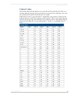
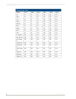
Page 17: ... mode the Mio R3 is in from selecting Device 1 Device 6 or a combination for extra devices Channel Codes Button Dev 1 Dev 2 Dev 3 Dev 4 Dev 5 Dev 6 PLAY q 1 41 81 121 161 201 STOP w 2 42 82 122 162 202 PAUSE e 3 43 83 123 163 203 FFW t 4 44 84 124 164 204 REW i 5 45 85 125 165 205 S FFD y 6 46 86 126 166 206 S REV u 7 47 87 127 167 207 REC p 8 48 88 128 168 208 Power Symbol 9 49 89 129 169 209 0 1...

Page 18: ... 196 236 EXIT 37 77 117 157 197 237 GUIDE 38 78 118 158 198 238 INFO 39 79 119 159 199 239 LAST 40 80 120 160 200 240 TV Device 1 241 241 241 241 241 241 SAT Device 2 242 242 242 242 242 242 DVD Device 3 243 243 243 243 243 243 CD Device 4 244 244 244 244 244 244 AUX Device 5 245 245 245 245 245 245 LGHT Device 6 246 246 246 246 246 246 A Macro 1 250 250 250 250 250 250 B Macro 2 251 251 251 251 2...

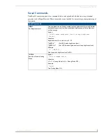
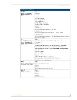
Page 19: ...sed to customize the brightness of the red LEDs that backlight the power button if the predefined brightnesses in Setup Mode are not fine enough Syntax BRIT awake brightness level sleep brightness level Variables brightness level a value from 0 32 BRT Set LED Awake brightness level BRT Set LED Awake brightness level sleep brightness level Example 1 BRT 16 Sets the awake brightness level to 50 CFG ...

Page 20: ...ariables variable text address range 1 the address range corresponds to the dynamic line number only one line is supported on this device Example SEND_COMMAND Panel FML 1 D L Set line 1 to a Dynamic line with level FML D L Sets a line of the display to a dynamic line with a level and sets the level style Syntax FML variable text address range D L Level Style Variables variable text address range 1...

Page 21: ...ing a numeric keypad layout for those buttons with a defined address range Syntax JST variable text address range new text alignment Variable variable text address range 1 the address range corresponds to the dynamic line number only one line is supported on this device new text alignment Value of 1 9 corresponds to the following locations 1 4 or 7 Left 2 5 or 8 Center 3 6 or 9 Right Example SEND_...

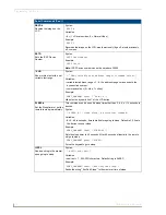
Page 22: ...ow Example SEND_COMMAND Panel SHO 1 0 Hides text on dynamic line 1 of the LCD button SLEEP Set the Sleep timer or put the remote to sleep immediately This command can be used if a sleep time other than 3 6 9 or 12 seconds is desired Syntax SLEEP timed sleep a persistent command Variables 0 60 in seconds time to wait before going to sleep Default is 30 0 sets the device to never sleep Example SEND_...

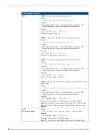
Page 23: ...vt addr range new text Variables variable text address range 1 button states range 1 256 for multi state buttons 0 All states for General buttons 1 Off state and 2 On state new text 1 50 ASCII characters Example SEND_COMMAND Keypad TXT 1 Test Only Sets the On and Off state text for the display UNI Set Unicode text For the UNI command UN and BMF command the Unicode text is sent as ASCII HEX nibbles...

Page 24: ...turns to default and all parameters that can be set in Setup Mode are reset to their default value ZAP MENU Sets the text displayed on the LCD for the six devices to the default values ZAP FONT Erases the font from the flash NOTE These commands are intended for serial use only These commands cannot be issued when the device s Setup Page is open ZIGC Sets the ZigBee Channel Syntax ZIGC channel Deci...

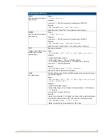
Page 25: ...sleep brightness level Variables a value from 0 32 BRT Set LED Awake brightness level BRT Set LED Awake brightness level sleep brightness level Example BRT 16 Sets the awake brightness level to 50 BRT 32 5 Sets the awake brightness level to 100 and sleep brightness level to approximately 15 CFG Enable or Disable Debug Mode Syntax CFG command value Variables 1 Debug Mode ON 0 Debug Mode OFF Example...

Page 26: ...riables variable text address range 1 the address range corresponds to the dynamic line number only one line is supported on this device Example SEND_COMMAND Panel FML 1 D L Set line 1 to a Dynamic line with level FML D L Sets a line of the display to a dynamic line with a level and sets the level style Syntax FML variable text address range D L Level Style Variables variable text address range 1 ...

Page 27: ...ide on dynamic line 1 of the LCD button Note There is no vertical alignment NUMD Sets the number of devices to be controlled by the remote Syntax NUMD numberOfDevices Example NUMD 1 Sets the remote to control only one device REBOOT Reboots the unit Syntax REBOOT Example SEND_COMMAND Panel REBOOT Forces the device to reboot SETD Sets the ICSP Device Number Syntax SETD deviceNum Example SETD 10020 S...

Page 28: ...SSL Sends a string to the master upon going to sleep Syntax SSL new text Variables new text 1 20 ASCII characters Default string is SLEEP Example SEND_COMMAND Panel SSL KeyPad Sleep Sends the string KeyPad Sleep to the master at time of sleep SST Sends a string to the master upon start up Syntax SST new text Variables new text 1 20 ASCII characters Default string is STARTUP Example SEND_COMMAND Pa...

Page 29: ...de text For the UNI command the Unicode text is sent as ASCII HEX nibbles Syntax SEND_COMMAND DEV UNI vt addr unicode text Variables variable text address range 1 unicode text Unicode HEX value Example SEND_COMMAND Keypad UNI 1 00 41 Sets the button s unicode character to A Note To send the variable text A in Unicode to all states of the variable text button 1 for which the character code is 0041 ...

Page 30: ...Programming The Mio R 3 26 Mio Modero R 3 Remote ...

Page 31: ...e Charging Base The Mio remotes are complemented with a Mio RCC charging base FG147 02 Specifications FIG 6 Mio RCC Charging Base FIG 7 Mio Remote Charging Base Top and Bottom view Rubber feet Angle barrel power connector Charging contacts Bottom View Top View ...

Page 32: ...e charging base The Power LED on the Mio remote blinks red to indicate it is charging and illuminates solid red when it is done Full charge cycle for a depleted battery is approximately 3 hours Mio RCC Remote Charging Kit FG147 03K with Base FG147 02 Specifications Dimensions HWD Charging Base 1 61 4 09 cm height 4 25 10 80 cm diameter Lithium Ion Battery 2 13 x 1 38 x 28 5 41 cm x 3 45 cm x 71 cm...

Page 33: ...Mio Remote Charging Base 29 Mio Modero R 3 Remote ...

Page 34: ...registered trademarks of AMX AMX reserves the right to alter specifications without notice at any time It s Your World Take Control 3000 RESEARCH DRIVE RICHARDSON TX 75082 USA 800 222 0193 469 624 8000 469 624 7153 fax 800 932 6993 technical support www amx com ...

Reviews: