

QUICK START GUIDE
ENOVA DVX-225xHD
6x3 All-in-One Presentation Switcher
Overview
This guide applies to the following Enova DVX-225xHD 6x3 All-in-One Presentation
Switchers:
• DVX-2250HD-SP (
FG1906-11
)
• DVX-2250HD-T (
FG1906-13
)
• DVX-2255HD-SP (
FG1906-12
)
• DVX-2255HD-T (
FG1906-14
)
The purpose of this document is to illustrate how to set up a device in its simplest
configuration by a trained technician.
What’s in the Box?
The following items are included with the DVX-225xHD:
• (1) Power Cord, Universal
• (1) Commoning Strip, Cypher, 8 Pos., 3.5 mm, Phoenix Connector
• (2) Front Rack Mounting Brackets
• (8) #8-32 x .375 screws
• (4) rubber feet
• (2) CC-NIRC, IR Emitter with 3.5mm Phoenix Connector (
FG10-000-11
)
• (1) CC-DVIM-VGAF, DVI to HD-15 Female Adapter (
FG10-2170-13
)
Power
IEC Power Cord Connector, ~100-240 VAC, 50/60Hz
Environmental Requirements
The environmental requirements for the DVX are as follows:
•
Operating Temperature
: 32° F (0° C) to 104° F (40° C)
•
Storage Temperature
: 4° F (-15° C) to 140° F (60° C)
•
Operating Humidity
: 5% to 85% RH
Getting Connected
Once the DVX is powered on, you can connect to it through its IP address.
NOTE: The DVX fully supports IPv6 network addressing. If the LAN port is connected to an
IPv6 capable network it will self select an appropriate IPv6 address based on the
discovered address parameters of the network to which it’s attached.
Locating the IP Address of the DVX
You can locate the IP address of the DVX by using the buttons on the front panel of the
unit. The IP address appears on the LCD display on the front panel of the DVX. Perform
these steps to locate the IP address of the unit:
1.
Press the STATUS button on the front panel of the unit to open the Status Menu.
The Status options appear on the LCD display.
2.
Use the UP and DOWN navigational arrow buttons to navigate through the
options until you find the IP address. Note the IP address for future reference.
NOTE: You can use the Status menu to verify current TCP/IP settings using the UP and
DOWN navigational buttons.
Switching to Static or Dynamic IP Addressing
To toggle between static or dynamic IP addressing, the controller cannot be currently
booting or it must be in ID Mode. If these conditions are met, holding the ID pushbutton
for 10 seconds changes the current IP addressing mode.
Changing the IP Address Once You Are Connected
Perform these steps to change the IP address once you are connected to the controller:
NOTE: Ensure the PC you are using to connect to the controller has the latest version of
NetLinx Studio 4.0 installed on it.
1.
Set the IP address on your PC to the same network the controller is currently on.
2.
In NetLinx Studio, select
Diagnostics > Network Addresses
from the menu bar to
open the Network Addresses dialog.
3.
Click
Get IP Information
to enable the fields for editing.
4.
Enter the System, Device (0 for NetLinx Masters), and Host Name information.
5.
To specify a network IP address, select
Specify IP Address
.
6.
Enter the IP parameters into the available fields.
7.
Click
Set IP Information
to retain the pre-reserved IP Address to the Master.
8.
Click
Reboot Device
to finish assigning the IP address to the Master, and click
OK
to close the dialog.
Default Settings
The following sections list the default settings for the controller.
Default User Names and Passwords
The following table lists the default user names and passwords for accessing the DVX
through NetLinx Studio or the WebConsole.
Default IP Addresses
The following table lists the default IP addresses for the DVX.
Configuration
All items in this section require accessing the front panel of the DVX.
Using the Front Panel Buttons
You can access the configuration settings for the DVX by using the VIDEO MENU, AUDIO
MENU, SWITCH, and STATUS buttons on the front panel of the DVX. Pressing any
button opens its respective menu on the LCD display on the front panel.
Press the TAKE pushbutton to implement an audio/video switch while you are in the
Switch menu on the LCD display. When in an audio or video menu, press the button to
cycle through audio and video inputs or outputs (depending on the menu.)
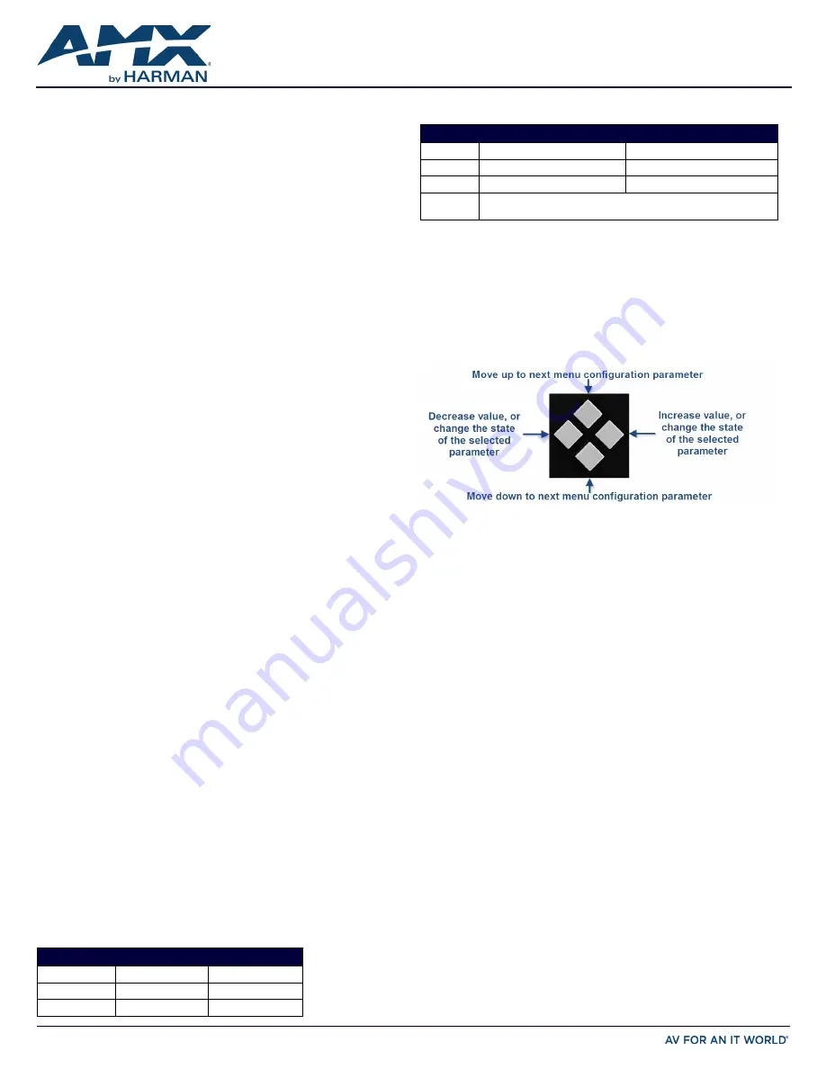
Use the Navigational buttons to traverse the available options and change their values.
FIG. 1 displays the navigational function of each button.
FIG. 1
NAVIGATION BUTTONS
Selecting a Video Test Pattern
Selecting a test pattern for your input source can help determine if you have your video
devices connected correctly. Perform these steps to select a test pattern:
1.
Press the VIDEO MENU button on the front panel of the DVX to open the Video
Output menu.
2.
Press the left and right navigation buttons to select the output on which to display
the test pattern (ALL, 1, or 2). (Note: You cannot display a test pattern on the
DXLINK output (3) from the front panel menu. Refer to documentation for the
DXLink receiver for information on displaying a test pattern from the receiver.)
3.
Press the down navigational button until the Output Test Pattern option appears.
4.
Use the left and right navigational buttons to select an appropriate output test
pattern.
Selecting an Audio Test Tone
Selecting a test tone for your input source can help determine if you have your audio
devices connected correctly. Perform these steps to select a test tone:
1.
Press the AUDIO MENU button on the front panel of the DVX to open the Audio
Output menu.
2.
Press the left and right navigation buttons to select the output on which to play
the test tone (ALL, 1, 2, or 3).
3.
Press the down navigational button until the Test Tone option appears.
4.
Use the left and right navigational buttons to select an appropriate audio test
tone.
Setting the Video Type for a Video Input
Each video input type must be set manually. Perform these steps to set the video type
for a video input:
1.
Press the VIDEO MENU button on the front panel of the DVX two times to open the
Video Input menu.
2.
Press the left and right navigation buttons to select the input to change. You can
select any input from 1-6.
3.
Press the down navigational button until the Type option appears.
4.
Use the left and right navigational buttons to select the video format for the
selected input. For Multi-Format inputs, you can choose from HDMI, DVI, VGA,
Component, S-Video, and Composite. The default setting is Component. For HDMI
inputs, you can choose from HDMI or DVI.
DEFAULT USER NAMES AND PASSWORDS
User Name
Password
NetLinx Studio
netlinx
password
WebConsole
administrator
password
DEFAULT IP ADDRESSES
IP Address
Subnet
Static IP
192.168.1.3
255.255.255.0
ICSLAN
198.18.0.1
255.255.0.0
Link-local
169.254.x.y, where x and y are the least significant two octets of the MAC
address.


