background image

35

USER MANUAL

DCP-SRX

IDX

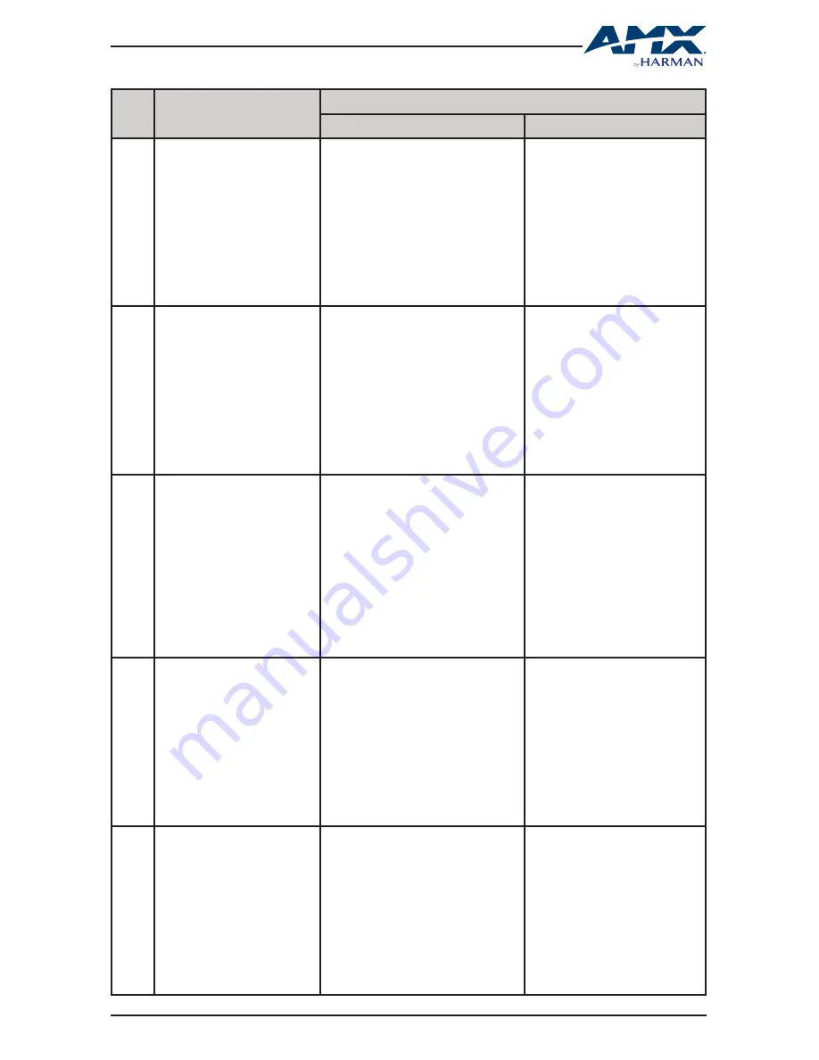
Function Description

More Details

Syntax

Example

11

Set CEC for Sink Power On/Off

Command:

CSP#T

Return:

CSP#T

Parameter:

 SP# : # = {0, 1} // {0, 1}:{off, on}

Description:

Control sink power on or off

Command:

CSP0T

Return:

CSP0T

Description:

Control for sink power off with 

HDMI out.

12

Set CEC Auto Power On/Off

Command:

CSPA#T

Return:

CSPA#T

Parameter:

 SPA# : # = {0, 1} // {0, 1}:{off, on}

Description:

Set sink auto power Function ON or OFF

Command:

CSPA1T

Return:

CSPA1T

Description:

Set sink auto power on.

13

Get CEC Auto Power Status

Command:

SSPAT

Return:

SSPAT( value )

Parameter:

 value = {0, 1} // {0, 1}:{off, on}

Description:

Get Sink auto power Function ON or 

OFF Status.

Command:

SSPAT

Return:

SSPAT( 1 )

Description:

Sink auto power status is ON.

14

Set CEC Power Delay Time

Command:

CD#SPT

Return:

CD#SPT

Parameter:

 D# : # = {0, 1, …30}

Description:

Set CEC Power Delay Time.

Command:

CD2SPT

Return:

CD2SPT

Description:

CEC Power Delay Time is 2 min.

15

Get CEC POWER Delay Time 

Status

Command:

SDSPT

Return:

SDSPT( value )

Parameter:

 value = {0, 1, …30} 

Description:

Get CEC POWER Delay Time Status.

Command:

SDSPT

Return:

SDSPT( 2 )

Description:

CEC Power Delay Time is 2 min.

Summary of Contents for DCP-SRX

Page 1: ...USER MANUAL DCP SRX 100m 4K HDBaseT Daisy Chain Scaling Receiver ...

Page 2: ...ar Panel 08 5 SCALER SWITCH 09 6 APPLICATION INSTALLATION 10 6 1 Typical Application 10 6 2 Installation Connection 10 7 CEC RS232 AUTO CONTROL 13 8 SET UP CONTROL 15 8 1 Web UI 15 8 1 1 Log Into Web UI 15 8 1 2 Control Through Web UI 16 8 1 2 1 Status 18 8 1 2 2 Configuration 18 8 1 2 3 Advanced 23 8 1 2 4 Device List 29 8 2 Telnet 29 9 RESET 31 APPENDIX API COMMAND SET 32 ...

Page 3: ...s ventilation openings with newspapers tablecloths curtains and similar items Do not install near any heat sources such as radiators heat registers stoves or other apparatus including amplifiers that produce heat Do not place sources of naked flames such as lighted candles on the unit Clean this apparatus only with dry cloth Protect the power cord from being walked on or pinched particularly at pl...

Page 4: ...s A SCALER switch is available for manual set up of output scaling parameter An extra USB connector is provided for power charging mobile phones tablets and the like For applications in need of a Scaling Receiver with great ease of control and versatility in connection DCP SRX is the choice DCP SRX offers a future ready Ultra HD A V switching and distribution solution and is ideal for collaboratio...

Page 5: ...5 USER MANUAL DCP SRX 2 PACKING LIST 1 x DCP SRX 1 x Power Supply 12 DVC 3A 2 x Phoenix Male Connectors 3 5 mm 3 pins 2 x Mounting Brackets 1 x User Manual this manual ...

Page 6: ...roma sub sampling 4 2 0 8 bit only for HDBaseT input Output 1 x HDMI OUT 1 x HDBaseT OUT Output Signal Type HDMI 2 0 with 4K HDBaseT Output Resolution HDMI 3840 x 2160P5 8 1920 x 12008 1920 x 1080P8 1280 x 10248 1280 x 8008 1280 x 720P8 1024 x 7688 Auto Scaler HDBaseT 1 VESA 800 x 6008 1024 x 7688 1280 x 7688 1280 x 8008 1280 x 9608 1280 x 10248 1360 x 7688 1366 x 7688 1400 x 10508 1440 x 9008 160...

Page 7: ... C 45 C 10 90 non condensing Storage Temperature RH 4 F 158 F 20 C 70 C 10 90 non condensing ESD Protection Human body model 8kV air gap discharge 4kV contact discharge Power Supply 12 VDC 3A Power Consumption 20 6 W Maximum Dimensions W x H x D 223 mm x 27 mm x 196 2 mm Weight 1 2 kg Certification CE FCC ...

Page 8: ...iption 1 HDBT IN Connect to HDBT OUT of any HDBT transmitter or DCP MTX or another DCP SRX 2 RS232 Connects to a controllable device e g projector for RS232 pass through control 3 ETHERNET Connects to a LAN device e g IP based touch panel for LAN control 4 HDMI OUT Connects to an HDMI display device 5 AUDIO OUT Connects to an audio system e g amplifier 6 SCALER switch Uses a DIP switch for adjust ...

Page 9: ...d scaling output resolution by using the SCALER switch 0 1 1 2 ON DIP 3 4 Default Auto Scaler DIP SWITCH SETTINGS SCALING OUTPUT RESOLUTION 0 0 0 0 Auto Scaler Default 0 0 0 1 Fix 1024 x 768 60Hz 0 0 1 0 Fix 1280 x 720 60Hz 0 0 1 1 Fix 1280 x 800 60Hz 0 1 0 0 Fix 1280 x 1024 60Hz 0 1 0 1 Fix 1920 x 1080 60Hz 0 1 1 0 Fix 1920 x 1200 60Hz 0 1 1 1 Fix 3840 x 2160 30Hz 1 0 0 0 Fix 3840 x 2160 60Hz 1 0...

Page 10: ...DBaseT HDBaseT HDBaseT DCP SRX N DISPLAY N HDBaseT Chain Mode DCP MTX 1 DCP MTX 2 DCP SRX 1 DCP SRX 2 SOURCE 1 SOURCE 2 DCP MTX N SOURCE N DISPLAY 1 DISPLAY 2 HDBaseT HDBaseT HDBaseT HDBaseT HDBaseT DCP SRX N DISPLAY N HDBaseT Ring Mode 6 2 Installation Connection To create a Chain or Ring type connection of multiple DCP MTXs DCP SRXs sources and displays please refer to the instructions below and...

Page 11: ...t of the first DCP MTX e g DCP MTX 1 b Login Web UI through a web browser Default IP address of DCP MTXs is192 168 1 121 c Go to Configuration Device Daisy chain Sequence Select Daisy chain quantity and click Start Sequence to allocate IP addressing to each DCP device 3 Connect source and display devices to DCP MTXs 4 Connect an HDMI display device to HDMI OUT of each DCP SRX If audio output is re...

Page 12: ...P MTX N HDMI LAPTOP VGA AUDIO LAPTOP DP LAPTOP HDMI MONITOR ETHERNET TOUCH PANEL IO KEY PAD HDBT HDBT HDBT SYSTEM WIRING DCP SRX 1 ETHERNET ETHERNET HDMI AUDIO RS232 PROJECTOR AUDIO SYSTEM ETHERNET SWITCH PC WEB UI CONTROLLER E G NX 2200 ETHERNET DCP SRX 2 HDMI AUDIO RS232 PROJECTOR AUDIO SYSTEM DCP SRX N HDMI AUDIO RS232 PROJECTOR AUDIO SYSTEM HDBT HDBT HDBT 1 DCP SRX should be used with DCP MTX ...

Page 13: ...P SRX will power on the display see flow chart below 1 If active input signal is present DCP SRX will send a CEC RS232 command to power on the display connected to HDMI OUT RS232 port immediately Detect for active input signal HDBT 1 DCP SRX Display HDBaseT HDBaseT DCP SRX Display HDBaseT HDBaseT Power on the display immediately when active signal is detected 2 HDBT DCP SRX will power off the disp...

Page 14: ...d 2 Cancel countdown 4 When active input signal is inserted 3 The display connected will shutdown 3 DCP SRX Display HDBaseT HDBaseT Display DCP SRX HDBaseT HDBaseT 30 30 Display DCP SRX HDBaseT HDBaseT 0 NOTE To realize CEC RS232 Auto Control of DCP SRX please connect a display device which accepts CEC RS232 command ...

Page 15: ...great ease and convenience The Web UI can be accessed through a modern browser e g Chrome Safari Firefox etc DCP SRX ships with a default IP address of 192 168 1 122 and default login password for Wen UI of admin 8 1 1 Log Into WEB UI To get accessed to Web UI of DCP SRX please follow the instructions below 1 Connect your PC to ETHERNET port of DCP SRX through a Catx Cable 2 Set your PC to the sam...

Page 16: ...the device using the RESET button For more information please go to 9 RESET 8 1 2 Control through WEB UI Web UI of DCP SRX is comprised by four sections Status Configuration Advanced and Device List The following menu tree shows the function structure of the Web UI which is followed by detailed introduction to each section ...

Page 17: ... Parity Bits Data Bits Stop Bits Hex String ON OFF End Flag RS232 Auto Control Delay Time RS232 Wakeup Command RS232 Standby Command RS232ManualControl Displayoff on RS232 Pass Through Baud Rate Parity Bits Data Bits Stop Bits Hex String ON OFF End Flag Command System Automatic Logout Firmware MCU ARM Scaler Factory Default Reboot Enable ON OFF Delay Time Welcome Menu Custom Web UI Logo Change Pas...

Page 18: ... but not in ID Mode Red gradient The DCP device is not connected Moving your mouse up onto a DCP device informaiton of the device will be displayed in a pop up window DCP SRX will show such informaiton as Name IP Address Sequence Grouping 8 1 2 2 Configuration The Configuration section includes Device Video Audio and Control and allows you to set up the DCP SRX input source signal and control meth...

Page 19: ...acters numbers space _ or 3 Daisy Chain Grouping The Daisy Chain Grouping section is for you to create small groups and is realized by switching on the Daisy Chain Grouping button and stopping signal from transmitting to downstream DCP devices Example To create Group A include DCP MTX 1 2 DCP SRX 1 and Group B include DCP MTX 4 DCP SRX 2 in a Ring Mode connection as below DCP SRX z DCP MTX 1 DCP M...

Page 20: ...P conflicts NOTE The DCP device will automatically reboot after the network setting is changed Video Audio The Video Audio sub menu is used to perform the following functions Scaling Output Setting Volume Mute 1 Scaling Output Setting The Scaling Output Setting button is used to adjust output resolution of DCP SRX By default the Scaling Output Setting of DCP SRX is in Auto Scaler mode the SCALER D...

Page 21: ...to its HDMI OUT port when CEC Auto Control is switched on Above all for CEC control of DCP SRX to be effective the display connected should support CEC over HDMI CEC Auto Control ON OFF Click to enable or disable CEC Auto Control When enabled the DCP SRX will send a CEC command to turn off the display connected to HDMI OUT when there s no signal present after a defined Delay Time or turn it on imm...

Page 22: ... port Hex String Switch the button ON to turn the RS232 commands to Hexadecimal format End Flag Click to choose the end flag for the RS232 commands Delay Time min Set the delay time of turning off the device after it receives RS232 command from DCP SRX The time is 0 30 minutes RS232 Wakeup Command Key in a user defined command for waking up the device connected then click the SAVE button RS232 Sta...

Page 23: ...a user defined command for controlling the device 8 1 2 3 Advanced The Advanced section includes Welcome Menu Password System Fireware and allows you to customize your own logo for your Web UI pages set up a new login password reset or reboot the DCP SRX settings enable disable automatic logout from Web UI and upgrade firmware of your DCP SRX device Welcome Menu The Welcome Menu section is for you...

Page 24: ...et the device using the RESET button on the rear panel For more information please go to 9 RESET System The System section is for resetting and rebooting the DCP SRX device as well as setting the Automatic Logout from the Web UI 1 System The System sub section is used for restoring the DCP SRX to factory default settings or rebooting the system Factory Default Click to reset the device to factory ...

Page 25: ...urns inactive Firmware The Firmware section is where the existing version of MCU ARM and Scaler can be verified and upgraded 1 To upgrade MCU To upgrade MCU please follow the instructions below Step 1 Click MCU Update button then the following window will pop up Step 2 Click Browse to search for the update file Then click Next to start uploading the update files NOTE Please mind the suffix h00 h01...

Page 26: ...When uploading is done the following appears Click Next to start updating Step 4 The MCU updating will take about two minutes Step 5 When completed the following window will appear After completion please reboot the device manually ...

Page 27: ...e instructions below Step 1 Click ARM Update button then the following window will pop up Step 2 Click Browse to search for the update file Then click Next to start uploading the update files Step 3 When uploading is done the following appears Click Next to start updating ...

Page 28: ...r completion please click to refresh 3 To upgrade Scaler To upgrade Scaler please follow the instructions below Step 1 Open the chassis and find out the wire feet used for scaler updating see 1 2 3 in the picture below Short circuit the feet Attach a USB flash drive contains Scaler update file to the USB connector on the front panel ...

Page 29: ... 8 1 2 4 Device List The Device List section lists out all the connected DCP devices by showing their model name and IP address Refresh Click to refresh the Device List Listed Device Click to navigate to its Web UI page 8 2 TELNET DCP SRX can also be controlled by Telnet a protocol that enables you to connected a remote or local computer with DCP SRX over a TCP IP network ...

Page 30: ...ured correctely For Telnet control the two network parameters of DCP SRX are required IP Address DCP SRX comes with a default IP address of 192 168 1 122 and may be changed after IP sequencing Please use the one after IP sequencing Port DCP SRX s fixed port number is 23 For complete list of controlling commands please go to APPENDIX API COMMAND SET ...

Page 31: ...cal RESET button on its rear panel and will restore the device settings and login password To reset DCP SRX 1 Hold down the RESET button rear panel for at least 5 seconds using a paper clip 2 The ID LED front panel will flash twice 3 Power cycle the device ...

Page 32: ...status Command CGRO0SW1T Return CGRO0SW1T Description Set current device subgroup 2 Get Subgroup Command SGROT Return SGROT value Parameter value 0 1 0 1 off on Description Get current device subgroup status Command SGROT Return SGROT 1 Description Current Device is Subgroup 3 Set ID LED Command CLED T Return CLED T Parameter LED 0 1 0 1 off on Description Indicates my current location Command CLE...

Page 33: ...0 100 Command CVA100T Return CVA100T Description Adjusts volume to 100 6 Get Volume gain Command SVT Return SVT value Description value 0 100 M Command SVT Return SVT 100 or SVT M Description Volume is at 100 If the status re sult is M the volume is muted 7 Audio Mute ON Syntax Command CVMT Return CVMT Description Mute the output Command CVMT Return CVMT Description Mute the output 8 Audio Mute OF...

Page 34: ... output resolution is 3840x2160 60 10 Get Output Resolution Command SRT Return SRT value Description value 1 8 11 18 0 1 18 1 Fix 1024x768 60 2 Fix 1280x720 60 3 Fix 1280x800 60 4 Fix 1280x1024 60 5 Fix 1920x1080 60 6 Fix 1920x1200 60 7 Fix 3840x2160 30 8 Fix 3840x2160 60 11 AUTO 1024x768 60 12 AUTO 1280x720 60 13 AUTO 1280x800 60 14 AUTO 1280x1024 60 15 AUTO 1920x1080 60 16 AUTO 1920x1200 60 17 A...

Page 35: ...A1T Description Set sink auto power on 13 Get CEC Auto Power Status Command SSPAT Return SSPAT value Parameter value 0 1 0 1 off on Description Get Sink auto power Function ON or OFF Status Command SSPAT Return SSPAT 1 Description Sink auto power status is ON 14 Set CEC Power Delay Time Command CD SPT Return CD SPT Parameter D 0 1 30 Description Set CEC Power Delay Time Command CD2SPT Return CD2SP...

Page 36: ... CUED T Parameter UED 1 2 3 4 1 2 3 4 null cr lf crlf Description Set UART End Character Command CUED4T Return CUED4T Description UART End Character is crlf r n 18 Set UART STOPBIT Syntax Command CUBI T Return CUBI T Parameter UBI 0 2 0 2 1bit 2bit Description Set UART Stop bit Command CUBI0T Return CUBI0T Description UART Stop bit is 1 19 Set UART Parity bit Command CUPA T Return CUPA T Parameter...

Page 37: ...elnet pass through Command CNE T Return CNE T Parameter NE hex1 hex2 hex64 hex1 hex2 hex64 hex1 hex2 hex64 is ASC II string of hex value For example string 123 convert to correct format string is 31 32 33 Description Set Telnet pass through Command CNE 00 01 02 03T Return CNE 00 01 02 03T Description Set Telnet pass through 22 Set UART Power On Off Command CUPW T Return CUPW T Parameter UPW 0 1 0 ...

Page 38: ...t UART Power Delay Time Command CPWD2T Return CPWD2T Description Set UART Power Delay Time to 2 min 26 Get UART POWER Delay Time Status Command SPWDT Return SPWDT value Parameter value 0 1 30 Description Get UART POWER Delay Time Status Command SPWDT Return SPWDT 2 Description UART POWER Delay Time Status is 2 min 27 Factory Reset Command SYSR Return SYSR Description Reset system setting Command S...

Page 39: ...x xx xx xx mask Command CIP192 168 1 122MASK255 255 2 55 0gw192 168 1 1T Return CIP192 168 2 122MASK255 255 2 55 0gw192 168 1 1T Description Set static IP address to 192 168 2 122 mask to 255 255 255 0 gateway to 192 168 1 1 31 Set DHCP IP Address Command CDHCPT Return CDHCPT Description Set DHCP IP Address Command CDHCPT Return CDHCPT Description Set DHCP IP Address 32 GET IP Address Command SIPT...

Page 40: ...marks registered trademarks of their respective companies AMX does not assume responsibility for errors or omissions AMX also reserves the right to alter specifications without prior notice at any time The AMX Warranty and Return Policy and related documents can be viewed downloaded at www amx com 3000 RESEARCH DRIVE RICHARDSON TX 75082 AMX com 800 222 0193 469 624 8000 1 469 624 7400 fax 469 624 ...

Reviews: