


Installation
16
MXD/T-1901-PAN 19.4" Modero X Series® G5 Touch Panels
3.
Cut out the surface for the back box.
4.
Thread the incoming power and Ethernet wiring from their terminal locations through the surface opening (FIG. 16
and FIG. 17).
Leave enough slack in the wiring to accommodate any re-positioning of the panel.
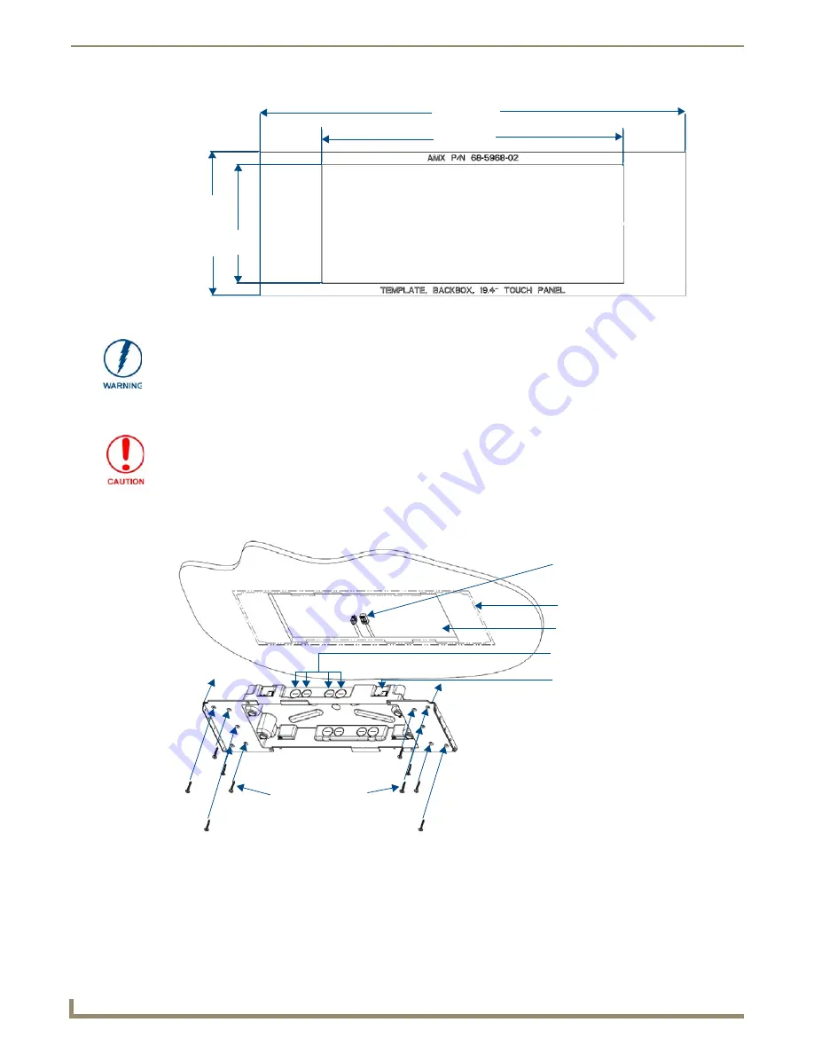
FIG. 15
MXD-1901-PAN Template
20.433"
519.00 mm)
6.89"
175.00 mm)
14.50"
368.30 mm)
5.69"
144.50 mm)
Using the included template to select the final placement of the back box is highly
recommended. The outside edges of the template are the same dimensions as the
touch panel, which allows you to troubleshoot possible conflicts with wall edges,
doors, and other potential obstacles.
Making sure that the actual cutout opening is slightly smaller than the provided
dimensions is highly recommended. This action provides the installer with a margin
for error if the opening needs to be expanded. Too little wall material removed is
always better than too much.
FIG. 16
MXD-1901-PAN Back Box installation (Landscape)
Cables routed
to wall opening
Knockouts
top)
Mounting screw
placement (optional)
Back box cutout
Outer edge of
back box
Locking tab


