


Installation
11
MXD/T-1901-PAN 19.4" Modero X Series® G5 Touch Panels
Installation
MXT-1901-PAN Installation
Other than the two USB ports on the back of the device (FIG. 3), the power and data connectors for the MXT-1901-PAN
are located on the underside of the device (FIG. 7). The underside USB port, as well as the two rear USB ports, may be
used with a flash drive for page transfers or firmware upgrades. Any USB peripherals (mouse, keyboard, etc.) may be
connected to one of the two USB ports on the rear of the device.
The MXT-1901-PAN does not have individual channels on the base of the device to allow passage of cables from
underneath the base. Instead, it has one slot at the base to allow options on cable configuration, with channels for
securing power and Ethernet cables (FIG. 8).
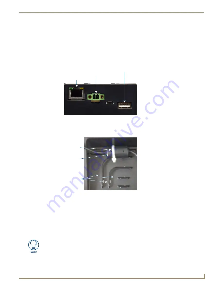
Each channel side has slots for attaching tie-wraps to secure each cable. The ferrite on the power cable must be secured
with the included tie-wrap during installation to prevent the possibility of the panel not sitting flush on the table. Other
cables may be secured with tie-wraps if desired, but this is not necessary.
Wiring Guidelines
The MXT-1901-PAN uses a 12 VDC-compliant power supply to provide power to the panel via the 2-pin 3.5 mm captive
wire PWR connector. Use the previously provided power requirement information in the
Specifications
table on page 3
to determine the power draw. The incoming PWR and GND wires from the power supply must be connected to the
corresponding locations within the PWR connector.
FIG. 7
MXT-1901-PAN underside connectors
FIG. 8
Tie-wrap for power connector ferrite
Ethernet 10/100
Port
USB Port
12 VDC
Power Port
Tie-wrap channels
Tie-wrap
Ferrite
Apply power to the panel only after installation is complete.


