background image

AXU-MSP Series and AXM-MSP32

Introduction

1

Introduction

Overview

The AMX UniMount Mini-SoftWire Panels (AXU-MSP) are microprocessor-
controlled pushbutton display units that can be programmed to control a wide
variety of equipment connected to an AXCESS system. The AXU-MSP series include
the AXU-MSP8, AXU-MSP16, AXU-MSP24, AXU-MSP32. The AXM-MSP32, which
contains the same pushbutton and bargraph configuration as the AXU-MSP32, can
be mounted into a 19-inch rack. This guide contains front and rear panel illustration
examples, programming instructions, installation procedures, panel specifications,
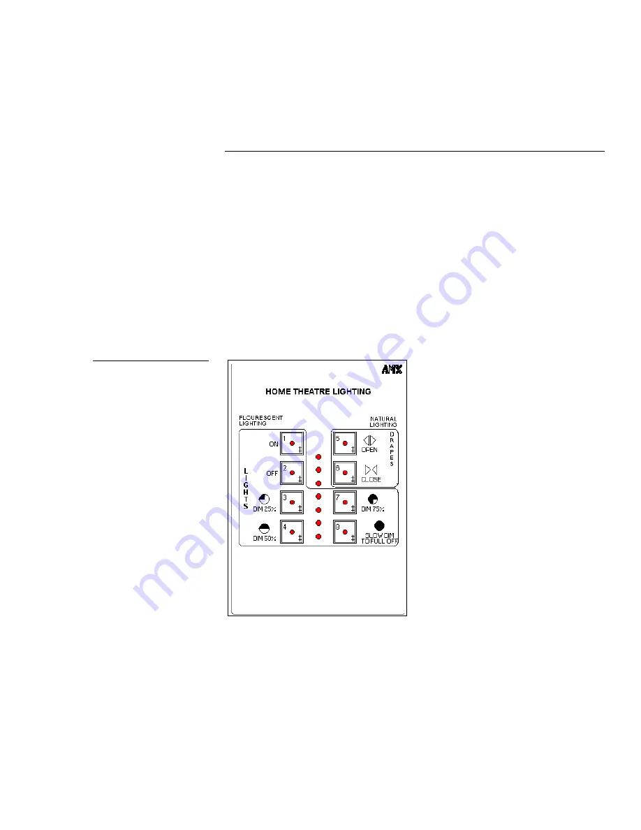
OLDesign overview, and technical support information. Figure 1 shows a sample
AXU-MSP8 panel.

Figure 1

Sample AXU-MSP8 panel

Summary of Contents for AXU-MSP16

Page 1: ... 80063 8QL0RXQW 0LQL06RIWZLUH 3DQHO 6HULHV DQG 00063065 QVWUXFWLRQ 0DQXDO LUHG RQWURO 3DQHOV ...

Page 2: ...ty or made by you for a third party This limitation of liability applies whether damages are sought or a claim is made under this warranty or as a tort claim including negligence and strict product liability a contract claim or any other claim This limitation of liability cannot be waived or amended by any person This limitation of liability will be effective even if AMX or an authorized represent...

Page 3: ...Programming 5 Overview 5 Push Displays 5 Pushbutton LEDs 5 Bargraph Programming 6 Bargraph Modes 6 Bargraph Mode Commands 7 LED Illumination Level Commands 7 Installation 9 Overview 9 Wall Podium and Rack Mounting Procedures 9 OLDesign Software Program 11 Overview 11 Features 11 Specifications 13 Overview 13 Technical Support 19 Overview 19 ...

Page 4: ...ii Table of Contents AXU MSP Series and AXM MSP32 ...

Page 5: ...tem The AXU MSP series include the AXU MSP8 AXU MSP16 AXU MSP24 AXU MSP32 The AXM MSP32 which contains the same pushbutton and bargraph configuration as the AXU MSP32 can be mounted into a 19 inch rack This guide contains front and rear panel illustration examples programming instructions installation procedures panel specifications OLDesign overview and technical support information Figure 1 show...

Page 6: ...ange control of multimedia presentation equipment Custom engraved panels Custom pushbutton functions and groupings Custom LED bargraph applications Installs into most standard wall box enclosures Front Panels Mini SoftWire Panel MSP pushbuttons can be programmed individually or in any combination as a single device or as a group The bargraph LEDs can also be programmed individually or as a group T...

Page 7: ...Pushbutton 5 Pushbutton 9 Pushbutton 13 Bargraph 1 Bargraph 2 Bargraph 3 Pushbutton 17 Pushbutton 21 Pushbutton 25 Pushbutton 29 Engraved overlay Pushbutton 1 Pushbutton 5 Pushbutton 9 Pushbutton 13 Bargraph 1 Bargraph 2 Bargraph 3 Pushbutton 17 Pushbutton 21 Pushbutton 25 Pushbutton 29 Engraved overlay Figure 3 AXU MSP24 panel Figure 4 AXU MSP32 panel Figure 5 AXM MSP32 rack mount panel ...

Page 8: ...The MSP rear panels contain the AXlink bus connector AXlink LED and the SIP switch that is used to set the panel s device number Figure 6 shows the back panel component configurations AXU MSP16 AXU MSP24 AXU MSP8 AXU MSP32 AXM MSP32 Figure 6 MSP rear panels ...

Page 9: ...el PUSH panel device number button number The pushbutton response appears in the AXCESS software program s PUSH window You can press the ALT and F keys on your keyboard to see what the pushbutton does in the software program You can also press the ALT and I keys to insert the pushbutton in the software program and enter the pushbutton s function Pushbutton LEDs Each LED in the panel s pushbuttons ...

Page 10: ...NEL 2 OF THE VOLUME CARD DEFINE_PROGRAM SEND_LEVEL MSP 1 MIC_LEVEL MIC VOLUME DISPLAYS ON FIRST BAR GRAPH THIS STATEMENT CAN BE ANYWHERE IN THE PROGRAM Bargraph Modes You can program panels using three bargraph modes bar mode dot mode and discrete mode Bar mode system default will activate LEDs in a bottom to top sequence Dot mode will only activate the peak LED of the display level Discrete mode ...

Page 11: ...s ON for level setting s 1 15 9 Inverse individual element discrete mode 4 Inverse normal bar mode Sequences from top to bottom 5 Inverse normal dot mode LED Illumination Level Commands Figure 10 lists the commands to set the LED illumination levels on the panel s pushbuttons and bargraphs DIM Dim mode 0 7 LED illumination level commands Mode Description Mode Description 0 100 percent duty cycle d...

Page 12: ...8 AXCESS Programming AXU MSP Series and AXM MSP32 ...

Page 13: ...n your system typically use device numbers 128 through 255 for the panels Figure 11 shows a SIP switch example set to device number 129 1 128 129 and the values for each SIP switch position 1 2 3 4 5 6 7 8 ON Switch 1 2 3 4 5 6 7 8 ON Value 1 2 4 8 16 32 64 128 3 Locate and connect the AXlink data and power bus to the panel as follows a Strip 25 inch of insulation off each wire and tin the ends wi...

Page 14: ...nnections Afterwards reconnect the AXlink connector to the panel and verify the LED is flashing once per second 5 Locate the slot on the front panel and gently remove the overlay from the faceplate 6 Place the panel in the wall wall box podium or rack and align the screw holes with the mounting holes on the panel 7 Fasten the panel to the wall wall box podium or rack using the screws supplied with...

Page 15: ...criptions are used when the panel and AXCESS operating software is programmed OLDesign also contains an on line help system that provides operating instructions you can use to produce custom overlay designs and pushbutton descriptions and then store them on your computer Figure 13 shows the OLDesign main window and Figure 14 shows a sample AXU MSP8 overlay design Refer to the OLDesign for Windows ...

Page 16: ...12 OLDesign Software Program AXU MSP Series and AXM MSP32 Figure 14 Sample AXU MSP8 overlay design ...

Page 17: ...e 23 shows the AXM MSP32 cutout dimensions and Figure 24 lists the specifications AXU MSP8 specifications Pushbuttons Bargraphs Power Enclosure Weight Dimensions HWD Mounting options Options Up to 8 black gray and or white pushbuttons in a two by four matrix One by eight LED bargraphs 12 VDC for AXlink 85 mA maximum per panel Metal with black matte finish 7 6 ounces 215 4 grams 4 5 x 3 18 x 1 0 11...

Page 18: ...four matrix Two one by eight LED bargraphs 12 VDC for AXlink 91 mA maximum per panel 4 pin captive wire compression connector Metal with black matte finish 10 5 ounces 297 7 grams 4 5 x 4 88 x 1 0 114 30 mm x 124 0 mm x 25 4 mm Wall mount using standard two gang wall box Podium mount Custom logo and panels Color text and borders on an engraved overlay Figure 17 AXU MSP16 cutout dimensions Figure 1...

Page 19: ...r matrix Three one by eight LED bargraphs 12 VDC for AXlink 100 mA maximum per panel 4 pin captive wire compression connector Metal with black matte finish 13 1 ounces 371 3 grams 4 5 x 6 68 x 1 0 114 30 mm x 169 7 mm x 25 4 mm Wall mount using standard three gang wall box Podium mount Custom logo and panels Color text and borders on an engraved overlay Figure 19 AXU MSP24 mounting dimensions Figu...

Page 20: ...r matrix Three one by eight LED bargraphs 12 VDC for AXlink 110 mA maximum per panel 4 pin captive wire compression connector Metal with black matte finish 1 04 pounds 16 6 ounces 4 5 x 8 48 x 1 0 114 30 mm x 215 4 mm x 25 4 mm Wall mount using standard four gang wall box Podium mount Custom logo and panels Color text and borders on an engraved overlay Figure 21 AXU MSP32 mounting dimensions Figur...

Page 21: ...lack gray and or white pushbuttons in a four by four matrix Three one by eight LED bargraphs 12 VDC for AXlink 110 mA maximum per panel 4 pin captive wire compression connector Metal with black matte finish 1 04 pounds 16 6 ounces 3 5 x 19 0 88 9 mm x 426 6 mm Rack mount Custom logo and panels Color text and borders on an engraved overlay Figure 23 AXM MSP32 rack mount Figure 24 AXM MSP32 rack mou...

Page 22: ...18 Specifications AXU MSP Series and AXM MSP32 ...

Page 23: ...the program from a new copy of your master disk If you still have a service problem refer to the chart Figure 25 and the map in Figure 26 to determine your team then call your AMX Support Team for technical assistance Sales and Support Team Telephone Numbers Team Telephone Number East 800 75 AMX 75 Central 800 85 AMX 85 West 800 55 AMX 55 Special Projects 800 45 AMX 45 International 1 972 907 6247...

Page 24: ...ns without notice at any time AMX and the AMX logo are registered trademarks of AMX Corporation All other trademarks contained in this document are the properties of their respective owners 11995 Forestgate Drive Dallas Texas 75243 800 222 0193 972 644 3048 Fax 972 907 2053 www amx com ...

Reviews: