


Chapter 1
Setting Up the MightyBoard 800
6
QuickStart Guide
MightyBoard 800
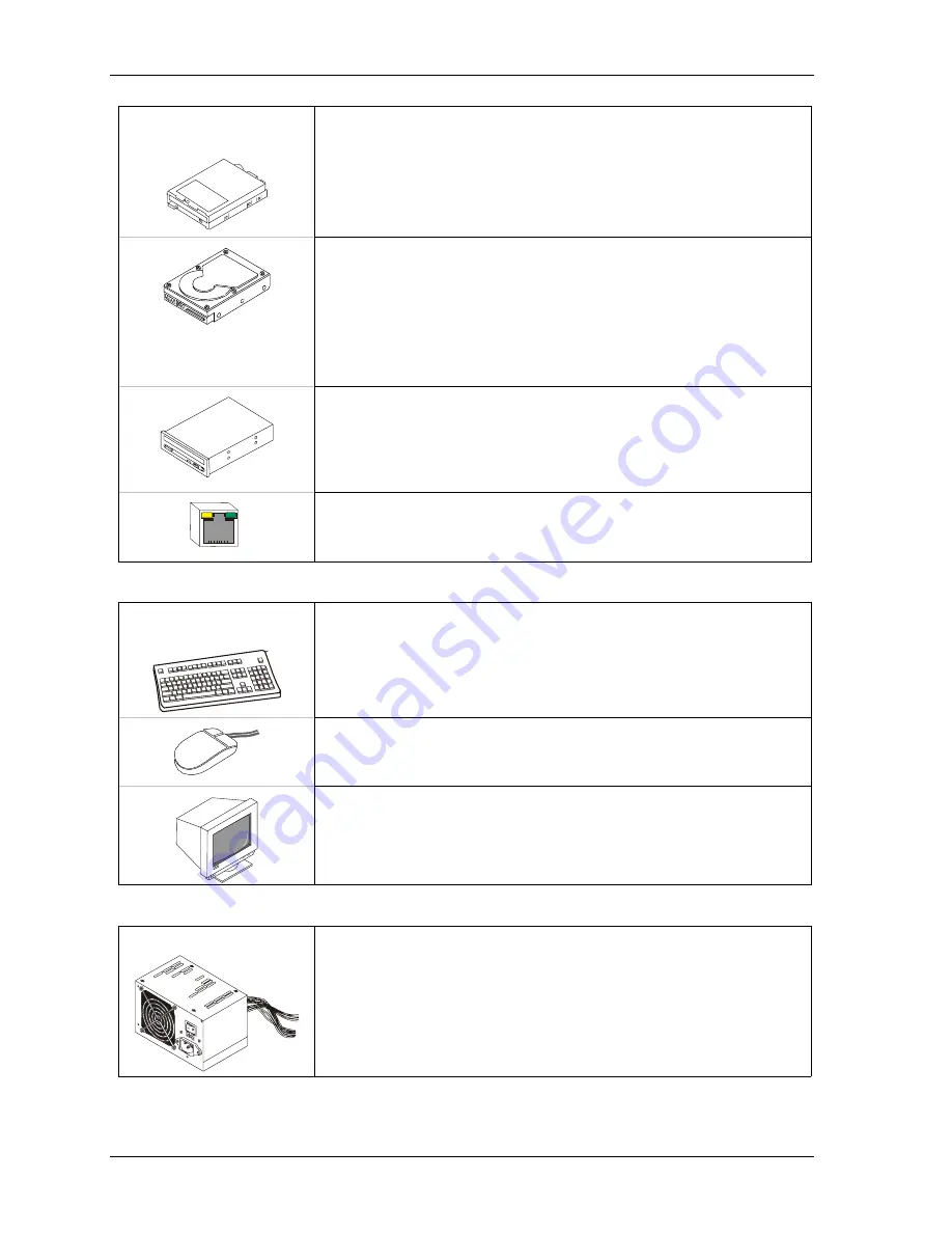
Connecting Boot Devices
7) Connect the OS boot
device(s)
•
Use one or all of the seven options listed here that apply when connecting
an (OS) boot device(s) to the MightyBoard 800:
a.
Connect a floppy disk drive to the floppy drive cable connected to J4 on
the edge of the MightyBoard 800. See Figures 1-1, 1-2, or 1-4.
Or
Connect a USB floppy drive to one of the USB ports,
Or
(See USB Boot Support Note at the end of this chapter.)
b.
Connect an IDE hard disk drive to a free connector on the primary IDE
cable (J14) on the edge of the MightyBoard 800. See Figures 1-1, 1-2,
or 1-4.
•
Ampro recommends not using a preinstalled OS on a hard disk drive to
boot and load the operating system. See Note with Step 16.
Or
Connect a USB hard drive to one of the USB ports,
Or
(See USB Boot Support Note at the end of this chapter.)
c.
Connect a CD-ROM drive to an available connector on the primary IDE
cable (J14) on the edge of the MightyBoard 800. See Figures 1-1, 1-2,
or 1-4.
Or
Connect a USB CD-ROM to one of the USB ports,
Or
(See USB Boot Support Note at the end of this chapter.)
Ethernet Connection
e. Connect an Ethernet cable to LAN 1 (J15A) for the PXE server, if you
are using the LAN Boot feature. Refer to Steps 13, 14 d & e, 15, and the
LAN Boot Note at the end of this chapter.
Connecting Peripherals
6) Connecting the
peripherals
•
Connect the Keyboard to the lower PS/2 connector at J1A. See Figure 1-1.
•
If your are using a USB keyboard, connect it to the USB 0 connector
(lower USB on J12B) on the edge of the MightyBoard 800.
•
Connect mouse cable to the upper PS/2 connector at J1B. See Figure 1-1.
•
If your are using a USB mouse, connect it to the USB 1 connector
(upper USB on J12B) on the edge of the MightyBoard 800.
•
Connect the CRT monitor to the video connector at J9 on the edge of
the MightyBoard 800. See Figure 1-1.
Connecting the Power Supply and Applying Power
8) Connect power supply
•
Connect the ATX power supply to the ATX Power-In connector (J3) on
the edge of the MightyBoard 800. See Figures 1-1 and 1-4.
•
Connect all support devices to the ATX power supply.
Ensure all of the support devices you have connected to the
MightyBoard 800 (except CRT) have good power connections to the
ATX power supply.
Summary of Contents for MightyBoard 800
Page 1: ...MightyBoard 800 Single Board Computer QuickStart Guide P N 5001775A Revision A...
Page 4: ...Contents iv QuickStart Guide MightyBoard 800...
Page 22: ...Chapter 2 Installing MightyBoard 800 Options 18 QuickStart Guide MightyBoard 800...
Page 24: ...Appendix A Technical Support 20 QuickStart Guide MightyBoard 800...
Page 25: ......
Page 26: ......


