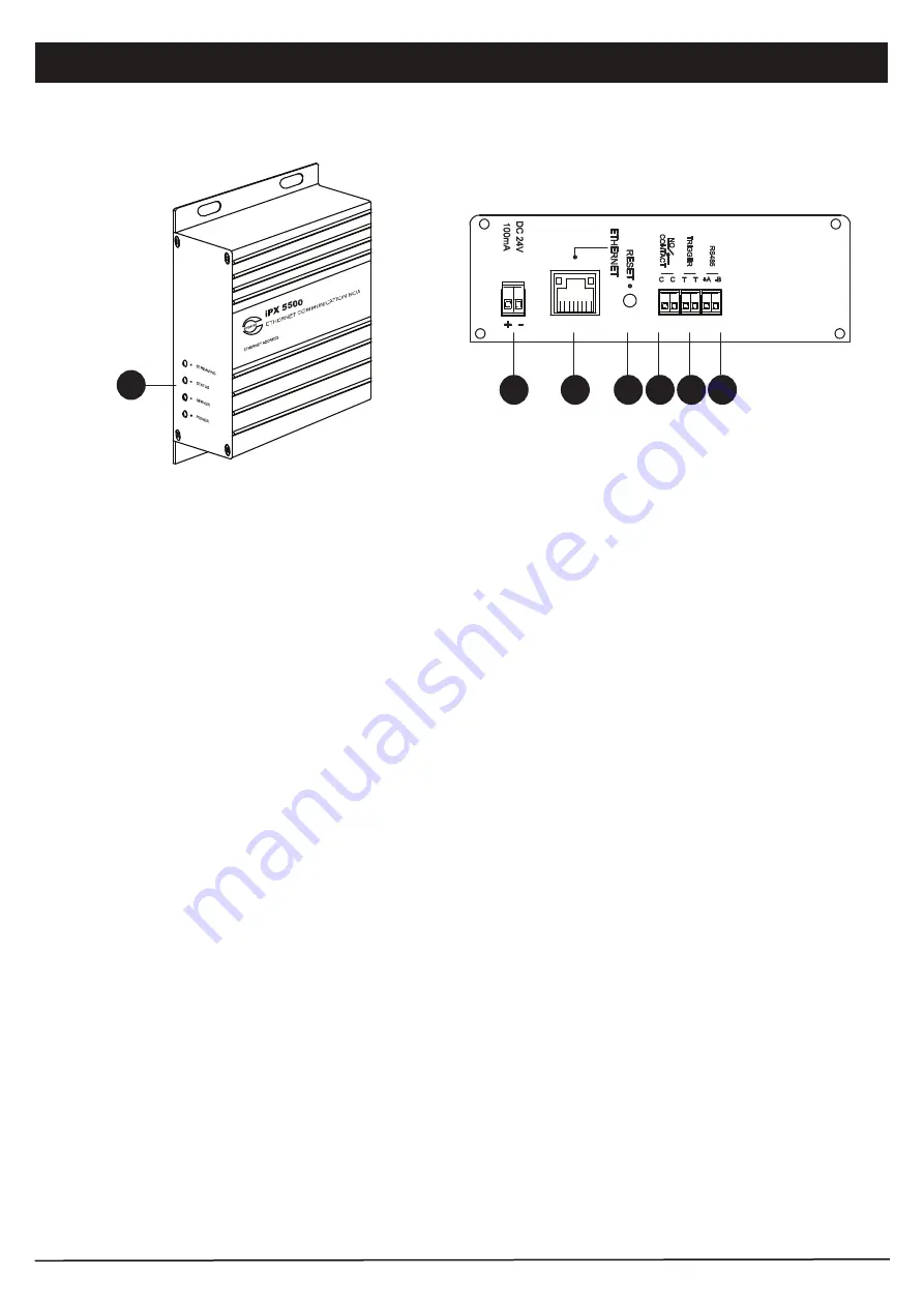
Parts Identification
2
PAGE 2
iPX5500 | ETHERNET COMMUNICATION BOX
3
6 7
1
1. INDICATOR LEDS
LEDs for Power, Server, Status and Streaming.
2. POWER PORT
24V DC power supply input.
3. ETHERNET PORT
Ethernet Port for connection to network switch.
4. RESET BUTTON
Button for resetting the unit to factory default. Use only when required as setting done previously would be lost.
5. RELAY CONTACT
This ports provide a dry contact which can be used to connect E/M overriding signal or activate ALL CALL at
speaker zone selector.
6. EXTERNAL MESSAGE TRIGGER PORT
Ethernet message player can be linked to it and can be broadcasted to the speakers when this port is triggered.
A voltage free contact is recommended to trigger the message playback.
7. RS485 PORT
Data port for connection to equipment to be monitored / controlled, such as QP Power Amp, BC9740 Battery Charger,
etc
Front View
Rear View
5
4


