


WHDI Reference Design Setup Guide
Dev Kit-UG1_Rev 1.0.28
on B1 when link is already in progress will disassociate. After disassociation the
system will automatically try to re-associate.
o
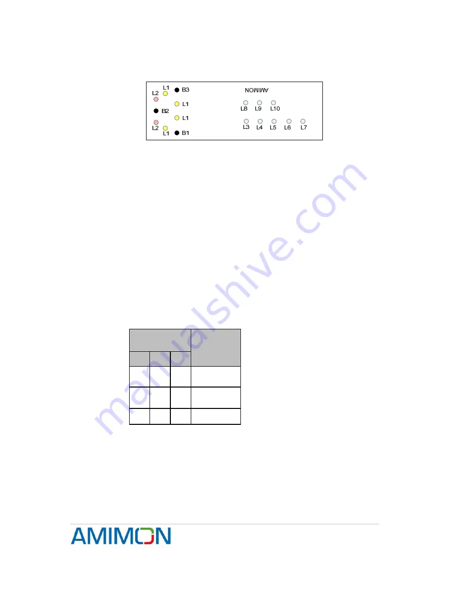
LEDs
: L1 is solid yellow once link is established.
o
Figure 5 - User Interface for Association
5.5 RF frequencies table selection
It is possible to configure the system to work with 3 different frequency pre-defined
tables, which are stored by default in the wireless board. The tables contain the
certified frequencies per the following regions: MIC, ETSI, FCC
To select a frequency table, follow the procedure below:
Press on the required buttons according to the table below and only then power up
the Seagull board. Wait until L2 LEDs are blinking.
1. Release the pressed buttons.
2. The Application will continue the boot process and will start working with the
desired frequency table
3. The Application keeps the table ID on its local EEPROM, so next boot same
frequency table will be used
Press one of the following buttons combinations before powering on the board
Buttons
combinations
B1
B2
B3
Freq group
(according
to region)
0 0 1 MIC
0 1 0 FCC
0 1 1 ETSI
5.6 Manual Transmission power (Tx only)
By default, the transmission power is set automatically. If for some reason the
automatic setting needs to be overridden, you may use the interface to disable the
TPC (Transmission Power Control) and set the transmission power manually.
Confidential
Under NDA
Internal document. Information subject to change
14
Page


