


57
Operation
Ramping Functions Example
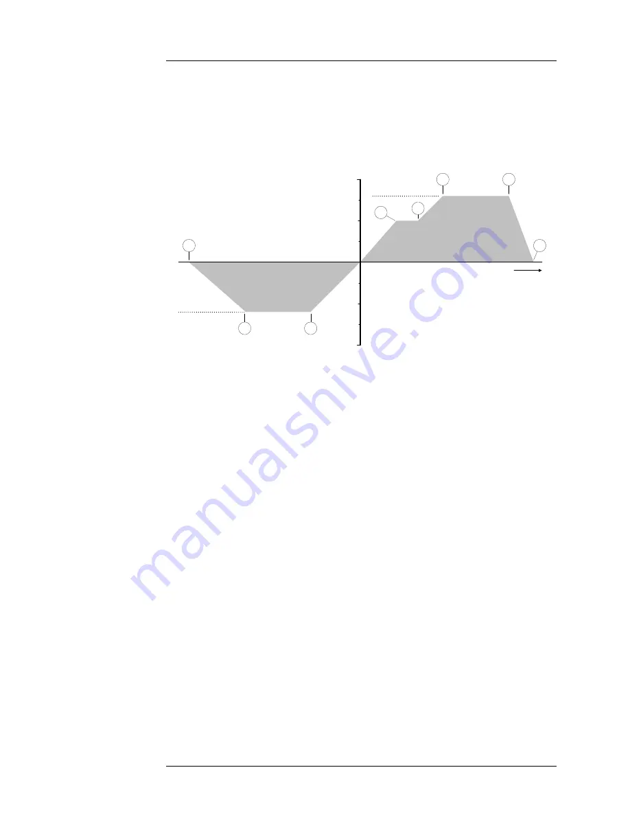
3.3.6 Ramping Functions Example
As an example of ramping to two programmed current settings, refer to
Figure 3-6 below. Each step is labeled as 1 through 8 in Figure 3-6. The
Model 420, for the purposes of the example, is assumed to be in the
PAUSED mode at 0 A at the beginning of the ramp.
Point 1. The operating current is 0 A and the Model 420 is in the PAUSED
mode. The operator sets the programmed current to -30.000 A. The
5$03
3$86(
key is pressed so that the PAUSED mode is no longer active and
the Model 420 begins ramping current.
Point 2. The programmed current setting of -30.000 A is achieved and the
Model 420 switches to HOLDING mode.
Point 3. The operator increases the ramp rate setting. The operator also
keys in a new value of +40.000 A for the programmed current setting. As
soon as the new programmed current is entered, the Model 420
automatically begins ramping at the specified ramp rate.
Point 4. The operator presses the
5$033$86(
key at an operating
current of 25.15 A and the PAUSED mode is activated. The Model 420
maintains the operating current in the PAUSED mode.
Point 5. The operator presses the
5$033$86(
key once again to resume
ramping.
Point 6. The programmed current setting of +40.000 A is achieved and the
Model 420 switches to HOLDING mode. At this point the operator
deactivates the persistent switch heater which removes the magnet from
the circuit.
1
4
6
7
8
2
3
PROGRAMMED
CURRENT 1
50 A
-50 A
PROGRAMMED
CURRENT 2
Time
5
Figure 3-6. Example of ramping to two different programmed current settings.
Summary of Contents for 420
Page 2: ......
Page 4: ......
Page 6: ......
Page 12: ...x Rev 7 List of Tables ...
Page 18: ...xvi Rev 7 Foreword Safety Summary ...
Page 22: ...4 Rev 7 Introduction Front Panel Layout ...
Page 24: ...6 Rev 7 Introduction Rear Panel Layout ...
Page 30: ...12 Rev 7 Introduction Operating Characteristics ...
Page 54: ...36 Rev 7 Installation Power Up Procedure ...
Page 82: ...64 Rev 7 Operation Summary of Operational Limits ...