Installation TW 5250 • TW 3500 • TW 1750
2-8 Elgar TrueWave
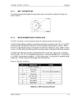
2.7.3 IEEE 488.2
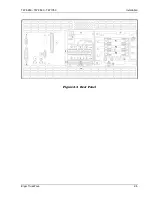
Refer to Figure 2-3, Item 6.
PIN # MNEMONIC PIN # MNEMONIC PIN #
MNEMONIC
1
DIO1
9
IFC
17
REN
2
DIO2
10
SRQ
18
GND (TW PAIR W/DAV)
3
DIO3
11
ATN
19
GND (TW PAIR W/NRFD)
4
DIO4
12
SHIELD
20
GND (TW PAIR W/NDAC)
5
EOI
13
DIO5
21
GND (TW PAIR W/IFC)
6
DAV
14
DIO6
22
GND (TW PAIR W/SRQ)
7
NRFD
15
DIO7
23
GND (TW PAIR W/ATN)
8
NDAC
16
DIO8
24
SIGNAL GROUND
Table 2-4 IEEE 488.2 Connector Pinout
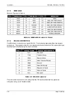
2.7.4 RS-232 CONNECTOR
The RS-232-C connector is a type DB-15S. The following table identifies the signals
and pinout. The signal common is not attached to frame within the TW series and must
be attached to the frame by the host controller.
PIN #
SIGNAL NAME
SIGNAL DESCRIPTION
1
N.C.
Not used
2
TXD
Transmit Data
3
RXD
Receive Data
4
DTR
Data Terminal Ready
5
GND
Ground
6
DSR
Data Set Ready
7
RTS
Request to Send
8
CTS
Clear to Send
9
N.C.
Not used
Table 2-5 RS-232 Connector
The connector is wired in such a way that the TW can be attached to a personal
computer using a null modem cable.

