Page 19
User Guide
Signal Processor
LMG GS
NOTE
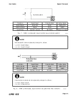
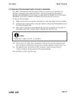
Keep wire length as short as possible.
2.3 System 4 Thermometer Cable Connector Assembly
The cable connectors for the rear panel of the processor are included in the
processor package. Each cable connector must be correctly wired with the
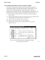
appropriate cable before the processor is used (refer to Section 2.2 for the cable
schedules). A ‘write on’ label is included in the connector for your use.
To wire up the connector.
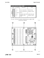
(i) Make a note of the connector’s orientation in the rear panel of the processor.
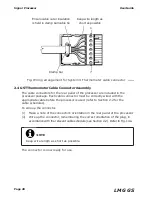
(ii) Unclip the two halves of the connector shell to reveal the terminal block and
the cable tie/clamp bar.
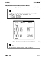
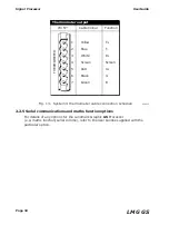
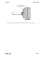
(iii) Wire up the connector, remembering the correct orientation of the plug, in
accordance with the relevant cable schedule (see Section 2.2).
(iii) Ensure that the cable outer insulation is held in the clamp bar/cable tie at
the connector and tighten the clamp bar screws/cable tie. Refer to Fig. 14.
(iv) Clip together the two halves of the connector shell ensuring that the
‘write on’ label is held in place by the shell assembly.
The connector is now ready for use.
Summary of Contents for Land LMG GS
Page 2: ......
Page 6: ......
Page 8: ......
Page 12: ...Page 4 Signal Processor User Guide LMG GS...
Page 35: ...Page 27 User Guide Signal Processor LMG GS Fig 20 Access code display 238020...
Page 62: ......


