


16
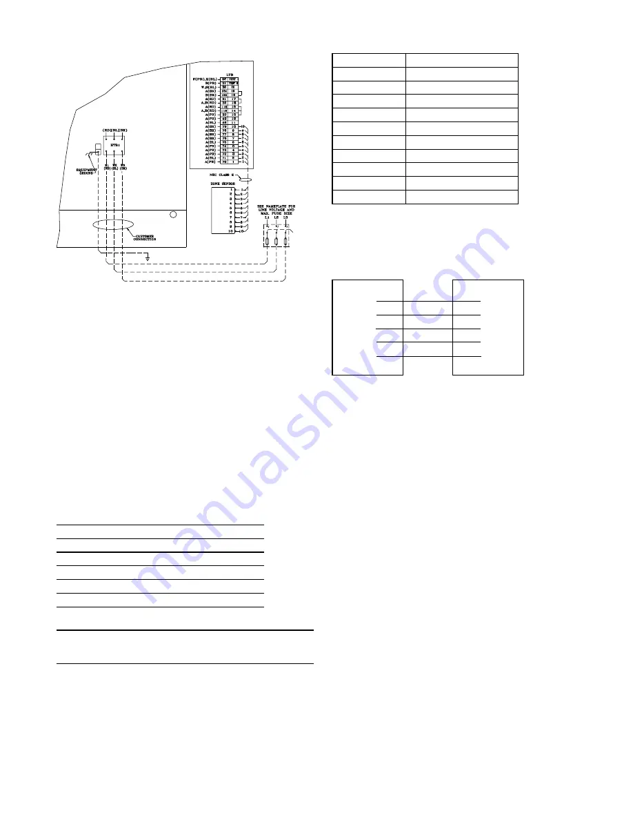
Figure 10
Typical Field Wiring Diagram
Low voltage control wiring must not be run in conduit with
power wiring. Route low voltage wire from zone sensor termi-
nals through 7/8 inch bushing in the unit. See dimensional
data for control wire entry location. Make connections as
shown by the appropriate low voltage wiring diagrams in Fig-
ure 10.
Zone Temperature Sensor conductors are standard thermostat
wire. The only exceptions are Tracer/Tracker installations
which utilize a serial communications link and require a
shielded twisted pair of conductors between the Tracer/
Tracker and the (TCI) Communications Interface.
Recommended wire sizes and lengths for installing the Zone
Temperature Sensor are provided in Table 5. Ensure that the
wiring between the controls and the unit's termination point
does not exceed two and a half (2.5) ohms/conductor for the
length of the run. Resistance in excess of 2.5 ohms per con-
ductor can cause deviation in the accuracy of the control.
Table 5.
DC Conductors
Wire size (mm2)
Maximum wire length (m)
0.33
45
0.50
76
0.75
115
1.30
185
2.00
300
NOTE: Do not run the electrical wires transporting DC
signals in or around conduit housing high voltage
wires.
Zone Temperature Sensor and low voltage terminal
designations are no longer R-W-Y-G-B etc, they are now 1-2-3
etc. Connections should be made using 1 to 1, 2 to 2, 3 to 3,
and so on. See following example.
Zone Temperature Sensor Terminal Strip
Terminal #
Terminal I.D.
1
ZTEMP
2
SIGNAL COMMON
3
CSP
4
MODE
5
HSP
6
LED COMMON
7
HEAT LED
8
COOL LED
9
SYS ON LED
10
SERVICE LED
Zone
Low
Sensor
Voltage
Module
Terminal Board
(ZSM)
(LTB)
1 [ ]
[ ] 1
2 [ ]
[ ] 2
3 [ ]
[ ] 3
4 [ ]
[ ] 4
5 [ ]
[ ] 5
Emergency Shut Down
For Emergency Shut Down, remove the jumper between LTB-
16 and LTB-17 and install normally closed contacts (Open at
Fault Condition). Immediate shut down will occur and the UCP
will be disabled.
Compressor Disable
To disable Compressor #1, remove the jumper between LTB-
13 and LTB-14 and install normally closed contacts (open to
disable).
To disable Compressor #2, (if applicable), remove the jumper
between LTB-14 and LTB-15 and install normally closed con-
tacts (open to disable).
Scroll Compressors
(125 - 250 Units only)
Because scroll compressors are uniquely different from tradi-
tional reciprocating compressors, their operating characteris-
tics and requirements represents a departure from reciprocat-
ing compressor technology.
Proper phasing of the electrical power wiring is critical for
proper operation and reliability of the scroll compressor.
Proper rotation of the scroll compressor must be established
before the unit is started. This is accomplished by confirming
that the electrical phase sequence of the power supply is cor-
rect. The motor is internally connected for clockwise rotation
with the inlet power supply phased A, B, C.
Summary of Contents for YK-IOM-2
Page 10: ...10 Figure 5 Figure 6 Detail of the Gas Section...
Page 17: ...17 Figure 11A Zone Sensor Interconnections...
Page 18: ...18 Figure 11B Conventional Thermostat Interconnections...
Page 23: ...23...
Page 24: ...24...


