American Standard YK-IOM-2 Installation Operation & Maintenance Download Page 14

14

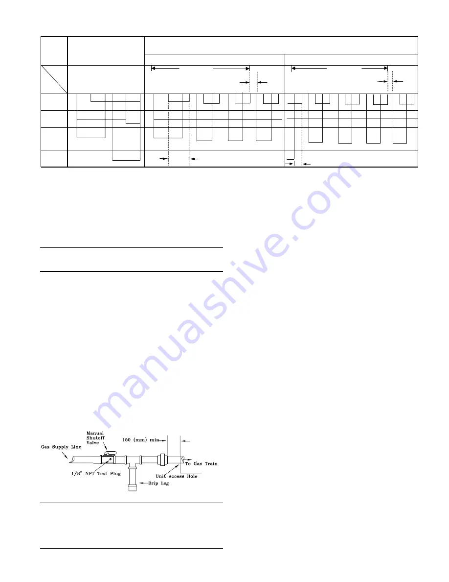
Figure 7- Trane Gas Heating Module Ignition Controller Start and Safety Sequence

Normal Sequence

Sequence With Safety Measures

(Stop by Regulation)

At Ignition with Flame Signal Fault

At Disappearance of Flame Signal

Time (s)

3 Retries 186.3 s

3 Retries 186.3 s

Operations

0

54

59.

7

60.

9

Manuel

R

egul

at

io

n

0

54

59.

7

62.

1

72min

etc..

0

0,

98

2

55

59.

7

62.

1

72min

etc..

Gas Valve

Fan

Electrode
Heating

Ionisation

TSA = 8,1s

TSE = 0,96S maxi

Use the following steps to complete the installation of the unit
gas piping. (See Figure 8)

1. Install a tapped, style A (1/8 inch NPT tap) shut-off gas cock

at the end of the gas supply line near the unit. Be sure the
tapped gas cock is downstream of the pressure regulator, if
used.

Note:  The shut-off gas cock must be installed
outside the unit, and should meet the specifications
of all applicable National and Local Codes.

2 . Install a ground union joint downstream of the shut-off

cock. This joint must be installed outside of the unit.

3 . Install a drip leg (at least 150 mm (6") in depth) next to the

union as shown in Figure 8. This drip leg is required to col-
lect any sediment that may be deposited in the line.

4 . Before connecting the piping circuit to the unit, bleed the air

from the supply line. Then cap or plug the line and test the
pressure at the tapped shut-off cock. The pressure reading
should not exceed 35 mBar (14 inches water column).

5. Connect the gas piping to the unit. Check the completed

piping for leaks using a soap and water solution, or equiva-
lent.

Figure 8
Gas Piping Schematic

IMPORTANT NOTE: THIS UNIT USES A NEGATIVE
REGULATION GAS VALVE. AT START-UP, THE
OUTLET PRESSURE SHOULD BE CHECKED AND
ADJUSTED IF REQUIRED TO A (NEGATIVE) -50Pa (-
0.2" OF WATER COLUMN.) NEVER ADJUST THE
REGULATOR TO A POSITIVE PRESSURE.

Manifold Pressure

The unit manifold pressure regulator (located on the gas
valve) is factory installed and adjusted to provide the rated unit
heating capacity. The required manifold pressure is factory set
at (negative) - 50 Pa (2 inches of water column) for natural
and LP gas.

Check the manifold pressure at the unit gas valve. Do not ex-
ceed the recommended pressure shown on the unit name-
plate.

Filter Installation

To gain access to filters, remove the evaporator fan access
panel. Each unit ships with 50 mm (2") filters. Number and
size of filters is determined by size and configuration of the
unit. Refer to the unit “Service Facts” for filter requirements.

Evaporator Fan Adjustment

Use the following procedure to determine the proper adjust-
ment of the evaporator fan sheaves for a specific application.

1. Determine total system external static pressure Pa (inches

of water column) with accessories installed. To accomplish
this:

a.  Obtain the design airflow rate and the design external
static pressure drop through the distribution system. Your
sales representative or the design engineer can provide
you with these values.

b. Using the table from the Service Facts, add the static
pressure drop of the accessories installed on the unit.

c. Add the total accessory static pressure drop (from step
1b) to the design external static pressure. The sum of
these two values is the total system external static
pressure.

2. Use the table(s) in the Service Facts to find the external

static pressure Pa (inches of water column) that most
closely approximates total system external static pressure.
Then locate the appropriate airflow rate (in m3/h) for your
unit. The value obtained represents the kW for the evapora-
tor fan motor and the fan RPM.

Summary of Contents for YK-IOM-2

Page 1: ...ould be done by qualified experienced technicians American Standard Inc 2000 Voyager TM Packaged Gas Electric 085 thru 250 Units INSTALLATION OPERATION MAINTENANCE Customer Property Contains wiring se...

Page 2: ...nstallation 14 Evaporator Fan Adjustment 14 Compressors 16 Pre Start Quick Check List 19 Power up Initialization 20 Unitary Control Processor UCP 20 Manifold Pressure 20 Final Installation Checklist 2...

Page 3: ...perature sensing function to the UCP Ignition Control Module There are two LED s located in the Ignition Control Module that monitor the operating status of the heater during the vari ous operating st...

Page 4: ...and control will revert to the zone sensor To terminate the test mode cycle the unit power at the unit disconnect Resistance Test Mode The resistance test mode is initiated by applying the appropri a...

Page 5: ...r Horizontal HORIZONTAL UNIT SI mm REAR VIEW SHOWING DUCT OPENINGS FOR HORIZONTAL AIR FLOW UNITS A B C D E F YK 085C 100C 406 413 510 76 162 914 YK 100B 125C 571 457 437 51 100 1053 YK 155B 175C 673 4...

Page 6: ...59 1509 2267 51 357 25 205 1205 1A YK 155B 175C 1692 1600 46 530 435 724 2588 1702 2597 51 357 25 191 1410 1A YK 200B 250B 2048 1956 46 565 591 725 2969 2057 2977 51 357 25 191 1765 Figure 1B Curb Dim...

Page 7: ...low or Horizontal Note Corner weights are given for information only Unit is to be supported continuously by curb or equivalent frame support Unit Support If unit is to be roof mounted check building...

Page 8: ...o closer than two feet from the unit to minimize noise and resistance Attaching Horizontal Ductwork to Unit All conditioned air ductwork should be insulated to mini mize heating and cooling duct losse...

Page 9: ...e K5 relay The burner fan then switches into high speed and the heating capacity is raised to maximum When the temperature of the zone has reached the setpoint the UCP de engerizes the relays K5 K6 H...

Page 10: ...10 Figure 5 Figure 6 Detail of the Gas Section...

Page 11: ...h due to electrical shock or contact with moving parts Measure the negative pressure downstream of the gas unit Connect a flexible hose to the gas unit branch connection and connect as electronic pres...

Page 12: ...onditioner 50 Hz EEC Voyager G20 41 4 92 49 1 91 70 6 90 77 4 91 G25 35 0 92 38 3 89 59 4 88 60 3 90 G31 37 7 92 48 6 90 57 3 88 78 2 92 YK 063CD X YK 073CD X YK 073DD X YK 085CD X YK 089CD X YK 100CD...

Page 13: ...Gas Flow 15 C 1013 mbar m3 h 4 7 5 3 8 3 8 2 Heat Rate kW 38 0 43 0 67 4 67 0 Reduce Rate Gas Flow 15 C 1013 mbar m3 h 4 5 4 9 7 8 7 9 Heat Rate kW 36 5 40 0 63 4 64 0 Natural Gas G31 30 37ou 50 mbar...

Page 14: ...AND ADJUSTED IF REQUIRED TO A NEGATIVE 50Pa 0 2 OF WATER COLUMN NEVER ADJUST THE REGULATOR TO A POSITIVE PRESSURE Manifold Pressure The unit manifold pressure regulator located on the gas valve is fa...

Page 15: ...cor dance with national and local codes Power Wiring The power supply lines must be run in weather tight conduit to the disconnect and into the bottom of the unit control box Provide strain relief for...

Page 16: ...ow 1 2 3 etc Connections should be made using 1 to 1 2 to 2 3 to 3 and so on See following example Zone Temperature Sensor Terminal Strip Terminal Terminal I D 1 ZTEMP 2 SIGNAL COMMON 3 CSP 4 MODE 5 H...

Page 17: ...17 Figure 11A Zone Sensor Interconnections...

Page 18: ...18 Figure 11B Conventional Thermostat Interconnections...

Page 19: ...plying unit After all electrical wiring is complete SET THE ZONE SEN SOR SWITCH TO THE OFF POSITION AND THE FAN SWITCH TO AUTO SO COMPRESSOR AND FAN WILL NOT RUN and apply power by closing the system...

Page 20: ...lock out Reset by disconnecting and re applying unit power Unit will start in the high fire mode After a short run cycle it will switch to low fire Note Blue smoke produced by the heat exchanger durin...

Page 21: ...this unit from the roof use the Test mode procedure on page 3 and 4 of this manual Operating Pressures After the unit has operated in the cooling mode for a short pe riod of time install pressure gaug...

Page 22: ...ons warrant Examine these areas of unit 1 Filters for cleaning or replacement 2 Motors and drive system components 3 Economizer gaskets for possible replacement 4 Condenser coils for cleaning 5 Safety...

Page 23: ...23...

Page 24: ...24...

Reviews: