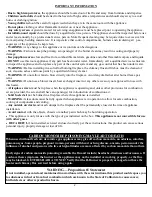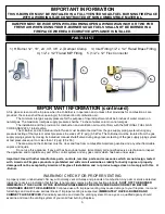
PARTS LIST
1.) H Burner 12”, 18”, 24’, 30”, 36” 2.) Damper Clamp 3.) Inlet Fitting 1/2” x 1/2” Flared Brass Fitting
4.) 1/2” x 1/2” Flared MIP Fitting 5.) 1/2” x 12” Flex Connector
IMPORTANT INFORMATION (continued)
A fire place screen must be in place when the H-Burner is in operation and, unless other provisions for combustion air are
provided, the screen shall have opening(s) for introduction of combustion air.
The minimum inlet gas supply pressure for the purpose of input adjustment shall be 6 inches of water column on
natural gas. The maximum inlet gas supply pressure shall be 7 inches of water column on natural gas .
The installation and the provision for combustion and ventilation air must conform with the NATIONAL FUEL GAS
CODE ANSI Z223.1 latest edition.
The H-Burner and its individual shutoff valve must be disconnected from the gas supply piping system during any
pressure testing of that system at test pressures in excess of 1/2 psig (3.5 kPa). The H-Burner must be isolated from the gas
supply piping system by closing its individual manual shutoff valve during any pressure testing of the gas supply piping system
at test pressures equal to or less than 1/2 psig (3.5 kPa).
The area around the H-Burner must be clear and free from combustible materials, gasoline and any other flammable
vapors and liquids.
Do not use this appliance if any part has been under water. Immediately call a qualified service technician to inspect
the appliance and to replace any part of the control system and any gas control which has been under water.
Important: Use with other manufacture parts, controls, remotes, parts and accessories which are not design, tested
with American Fireglass products is prohibited and will void all warranties. Liability for bodily injures or property
damage will not be accepted by American Fireglass if installation and / or product usage does not comply with this H
-Burner.
WARNING! CHECK FOR PROPER VENTING
A properly sized, unobstructed chimney will normally vent all fumes and products of combustion. Any odor or smoke detected
inside the room is an indication that the flue is not properly removing the combustion products.
SHUT OFF THE BURNER
IMMEDIATELY! THE CAUSE OF THE VENTING PROBLEM MUST BE DISCOVERED AND CORRECTED BEFORE
CONTINUED USE OF THE H-BURNER.
Continued use with improper venting may cause damage to your fireplace, room and
furnishings and could cause serious illness. If improper venting is suspected,
IMMEDIATELY HAVE H-BURNER AND
CHIMNEY FLUE SERVICED.
Periodically examine and clean the venting system. Once a year, a qualified agency should
examine and clean the venting system of your solid fuel burning fireplace.
3.
IMPORTANT INFORMATION
THIS H-BURNER MUST BE INSTALLED IN A FULLY VENTED SOLID-FUEL BURNING FIREPLACE
WITH A WORKING FLUE CONSTRUCTED OF NON COMBUSTIBLE MATERIAL.
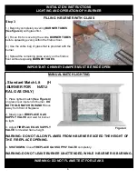
DAMPER MUST BE WIDE OPEN WHILE BURNING OPEN A WINDOW AN INCH OR TWO FOR
FRESH AIR WHEN USING YOUR H-BURNER SOLID FUELS SHALL NOT BE BURNED IN A
FIREPLACE WHERE A DECORATIVE APPLIANCE IS INTALLED.
1.
2.
3.
4.
5.


